

A broadcast tower’s job isn’t simply to stand tall; it must support transmitting antennas so their signals can cover the intended area. A radio tower may use a self-supporting structure or guy wires, depending on its design and site. In Australia, the Australian Communications and Media Authority regulates RF EME emissions from broadcast towers, which must comply with exposure limits in the ARPANSA RF Standard.
It’s easy to use “tower” and “mast” as if they mean the same thing, but their structures and support systems can differ. There is no single height limit that applies everywhere: the site, structure and applicable requirements all matter.
This article explains what broadcast towers do, how towers differ from masts, and how self-supporting and guyed designs work. It also covers factors affecting height and aircraft warning requirements, and summarises Australian rules for RF exposure and tower access.
Key Takeaways
- Identify whether a structure is a mast or tower by looking at how it stands and what supports it.
- Understand how guy wires and self-supporting designs affect the space and engineering needed for an antenna structure.
- Assess height and aircraft warning requirements in relation to the site and aviation considerations, rather than relying on a single universal limit.
- Learn how Australian RF exposure rules apply to broadcast sites, including why access near some AM tower bases is restricted.
- See how broadcast infrastructure differs from equipment used to improve mobile coverage or link separate sites wirelessly.
Aircraft warning lights and height limits
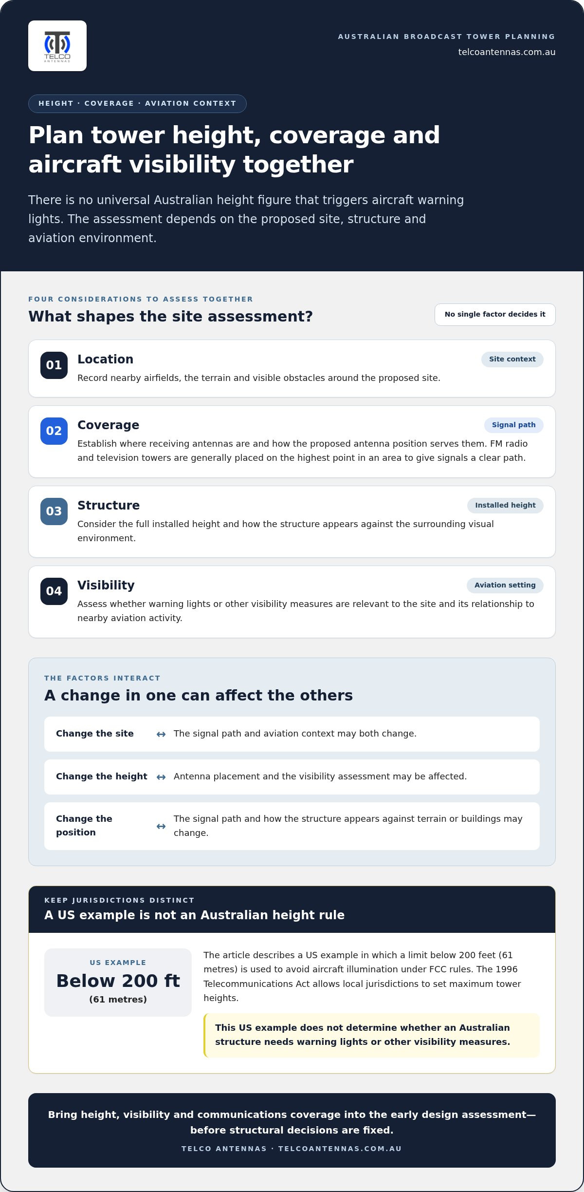
Aircraft warning lights help pilots see tall structures, particularly where a structure could affect aircraft movements. Whether lights or other visibility measures are appropriate depends on the proposed site and structure. A tower near an airfield presents a different planning situation from one in an isolated location. Height matters, along with position, terrain and the surrounding aviation environment.
There is no universal Australian height figure here that triggers lighting. Don’t apply a number from another country as if it were an Australian rule. Assess the proposed structure in its Australian setting, including its height, location and relationship to nearby aviation activity.
For an Australian project, consider visibility and height together during design. A structure’s position affects how it appears against terrain or other buildings, while its height and surroundings inform the aviation assessment. A threshold used in another jurisdiction cannot, by itself, determine what is appropriate for an Australian site.
Height also affects the communications task. FM radio and television broadcast towers are generally placed on the highest point in an area, giving signals a clear path to receiving antennas. Lowering an antenna or choosing another site can change the transmission path. Design needs to balance intended coverage with the structure’s position and aviation context.
During early planning, assess these elements together:
- Location: record nearby airfields, terrain and visible obstacles around the proposed site.
- Coverage: establish where receiving antennas are located and how the proposed antenna position serves them.
- Structure: consider the full installed height and the surrounding visual environment.
- Visibility: assess whether warning lights or other visibility measures are relevant to the site.
These considerations interact. Changing the site can affect both the signal path and aviation context; changing the height can affect antenna placement and visibility assessment. Bringing these questions together early helps clarify the design before structural decisions are fixed. The outcome should reflect the Australian site and its conditions, not a height threshold borrowed from elsewhere.
A comparison can help keep jurisdictional examples in their proper place. In the United States, the 1996 Telecommunications Act allows local jurisdictions to set maximum tower heights; one example is a limit below 200 feet (61 metres) to avoid aircraft illumination under FCC rules. That example describes a US approach, not a height standard for an Australian project. Its value is as a reminder that tower-height decisions can be governed by local planning choices as well as aviation considerations.
For an Australian proposal, the US example cannot determine whether a structure needs warning lights or other visibility measures. The assessment depends on the proposed location, structure and aviation environment. A project team can use the comparison to identify questions for early review, but should not transfer its limit to another jurisdiction or treat it as a substitute for a site-specific assessment. Keeping these distinctions clear helps prevent a foreign threshold from being mistaken for a local requirement. It also keeps the wider design task in view: consider tower height, visibility and communications coverage together before fixing the structure’s position and dimensions.
Alternative antenna supports
An antenna doesn’t always need a conventional steel lattice structure. Depending on the installation, it may be mounted on a rooftop frame, pole, building feature or portable mast. Each support affects the antenna’s position and how its load transfers into the building or ground. The equipment’s purpose and site conditions help determine which arrangement is practical.
A rooftop mount can position an antenna above nearby obstructions without using ground space for a freestanding tower. The roof structure, mounting point, antenna direction and cable route all affect the installation. For example, a roof-mounted antenna needs a suitable cable path to the associated equipment. The support must also suit the antenna’s size and the building’s structure.
A pole mount is another compact option for an antenna at a home, facility or communications site. Its position can be adjusted to suit the intended signal path, while the pole and its fixings must support the equipment. A building feature can also conceal or integrate communications equipment. In either case, the visible support and the antenna’s function are separate design considerations.
Material choice affects a support’s construction and appearance. Steel, aluminium, timber and other materials can be used for antenna structures, depending on the equipment, site conditions and design. Material alone doesn’t determine whether a support is suitable. Its shape, fixings, foundations or mounting surface, and the loads transferred through it all matter.
Portable supports serve a different purpose from permanent site structures. A tripod or temporary mast can hold an antenna for a field communications setup where the location or configuration may change. The support needs stable placement, suitable clearance and a workable cable route. For links between sites, a point-to-point wireless bridge uses directed antennas, making their alignment and the path between locations important.
- Rooftop frame: positions an antenna on a building, with mounting and cable routing shaped by the roof layout.
- Pole support: provides a compact mounting point for an antenna at a home or communications site.
- Integrated feature: can incorporate equipment into a building element or other site structure.
- Portable mast or tripod: supports temporary field equipment where a permanent structure isn’t needed.
For installations using multiple antenna elements, the support should hold the equipment in its intended arrangement. Telco Antennas’ MIMO antennas are relevant to systems using that configuration. Matching the support, antenna position and cable route helps keep the physical installation aligned with the communications task.
Broadcast tower regulation in Australia
Australian broadcast sites are subject to rules on radiofrequency electromagnetic energy (RF EME) exposure. Ownership, site conditions and equipment purpose also shape how a tower is used and managed.
There is no single standard cost for building or renting a tower in Australia. A build’s design, height, site access, foundations and equipment affect its requirements. Rental arrangements depend on the site and the space and facilities needed.
There is no single typical height for Australian radio towers. A broadcast structure’s height depends on its coverage objective, antenna position and terrain, while mobile and emergency communications sites serve different network needs.
Tower ownership and operation
Australian towers may be owned or operated by broadcasters, telecommunications network operators, site owners or infrastructure businesses. Ownership and operation can be separate: a site owner may provide the location while an operator manages transmission equipment. This distinction matters when identifying who controls access, equipment and site information. The operating organisation also helps explain a tower’s role in a local network.
Communication uses
Communication towers support broadcast transmission, mobile network coverage and links used by emergency services. Broadcast antennas transmit radio or television signals across a coverage area; mobile base stations connect devices to a network. Emergency communications equipment can also use elevated sites to maintain links across an area. Equipment and antenna configuration depend on the task, so don’t assume a structure’s role from its appearance alone.
Safety, maintenance and inspections
Safety considerations include RF EME exposure, restricted access, working at height and the physical condition of structures. The Australian Communications and Media Authority regulates RF EME emissions from broadcast towers, which must comply with exposure limits in the ARPANSA RF Standard. ARPANSA says current research indicates no established health effects from the low RF EME exposure the public encounters from broadcast towers. Ground-level exposure around FM and television broadcast towers is generally well below the public limit.
Access to the base of AM radio towers is restricted because exposure limits may be exceeded nearby. Maintenance and inspections assess structural condition, antenna mounts, cables and site equipment. Inspection frequency and work scope depend on the structure, equipment and operating conditions; there is no single inspection interval for every Australian tower.
To find nearby sites, search the RFNSA archive by location and review the available site details. Some records include a compliance certificate or site EME report, which can help explain the site’s exposure assessment and equipment context.
Differences between masts and towers
The main types of radio towers are guyed and self-supporting structures. A guyed mast relies on tensioned wires anchored around it, while a self-supporting tower carries its loads through its own frame and base. “Mast” and “tower” can overlap in everyday use, so the support method is often the clearer distinction.
A guyed structure uses wire stays to resist movement and transfer forces to ground anchors. At least three guy wires are required to provide tension in every direction. Their anchor points need space around the mast, affecting where the structure can fit. Guyed designs can reach substantial heights without the same broad structural frame as a self-supporting lattice tower.
A self-supporting tower stands without guy wires. Lattice members form a braced frame that transfers forces to the foundations. This arrangement can suit constrained sites where wire anchors would obstruct access or land use. A monopole is another self-supporting form: its single shaft takes up less ground space, though its structural design still needs to suit the equipment and site.
Structure type affects more than appearance. Antenna weight, wind loading, site access, available ground area and foundation conditions all influence the design. For example, an open site may accommodate the guy anchors a mast needs. A compact site may favour a self-supporting structure, whose tower and foundation must carry the loads without stays.
- Guyed mast: uses tensioned wires and ground anchors; at least three wires provide support in every direction.
- Self-supporting lattice tower: uses a braced frame and foundations, without guy wires.
- Monopole: uses a single self-supporting shaft, which can reduce the support footprint.
The difference also matters when assessing a structure’s surroundings. Guy wires extend beyond the mast and need clear anchor zones, while a self-supporting design concentrates support around the base. In either case, antenna position must suit the intended coverage and equipment layout. A structure designed for broadcast transmission may have different requirements from one carrying a point-to-point communications link.
For perspective, the Warsaw Radio Mast reached 646 metres and was a guyed structure. At least nine guyed masts taller than 600 metres have collapsed, illustrating why height alone cannot determine structural suitability. The design must account for the complete load path, from antenna and mast through wires or frame, into the foundations and surrounding ground. In practical terms, identifying the support system is the first step towards understanding how a particular mast or tower occupies and uses its site.
History of radio structures
Radio structures changed as broadcasters needed dependable ways to transmit signals. By 1930, broadcasters were adopting mast radiator antennas because T-antennas were expensive. This shift linked the supporting structure more directly with the broadcast system. It also illustrates how practical cost considerations influenced antenna design, not just the pursuit of greater height.
Television added a new role for elevated structures. In 1936, the BBC erected a television-broadcasting mast on a tower at Alexandra Palace in London. The structure remains in use. Its continuing service shows how a tower can support changing transmission needs over time, provided its structure and equipment remain suitable for operation.
Microwave networks prompted another design direction. In the 1950s, AT&T built numerous reinforced-concrete towers for its first transcontinental microwave route. These towers supported a communications system extending across a large distance. Their construction demonstrates that telecommunications infrastructure has included substantial concrete structures, as well as metal masts and lattice frames.
In 1956, civil engineer Fritz Leonhardt designed the Stuttgart TV tower, described as the world’s first tower built of reinforced concrete. Its material and engineering approach marked a distinct point in tower design. Rather than relying on a conventional steel framework, reinforced concrete provided the main structural form. The Stuttgart example shows how materials shape both construction and a tower’s visible profile.
Height records also reveal the engineering demands of supported structures. The Warsaw Radio Mast set a world record as the tallest structure on Earth in 1974. It collapsed on 8 August 1991, ending its status as the world’s tallest supported structure on land. The event is a reminder that exceptional height depends on the complete structure, including its supports and ongoing condition.
These examples show how radio broadcasting, television transmission and microwave communications have influenced structure design. They also show why a tower’s purpose matters when interpreting its form. A mast radiator, a television tower and a microwave-route structure serve different equipment arrangements, even though all support communications.
Modern links between separate sites can use directed wireless connections rather than relying only on broadcast transmission. For a communications design that needs a link between two locations, explore point-to-point wireless bridges as an option suited to that connection task.
When planning radio sites, designers also have to consider how much infrastructure already exists and how quickly a new structure can be erected. The United States has over 50 radio structures that are at least 600 metres tall. A carbon-fibre structure can be erected 40 - 50% faster than structures made with traditional building materials. Together, these facts add scale and construction speed to the considerations shaping a radio tower.
In 2022, a wooden telecommunications tower in Italy replaced an existing steel structure. The change is another example of material choice evolving while structures continue to serve communications needs. Alongside steel and reinforced concrete in earlier examples, wood and carbon fibre show that the history is not defined by a single structural material. Choices of material and construction speed sit alongside height and transmission purpose as considerations in the design of radio structures.
Telco Antennas: Cel-Fi GO Mobile Signal Boosters
Telco Antennas supplies Cel-Fi GO Mobile Signal Boosters for situations where mobile reception needs attention, rather than a new broadcast tower. The right communications setup depends on the signal environment, antenna placement and connected equipment.
For installations requiring antenna components, MIMO Antennas and LMR-400 Coaxial Cables can form part of the wider system. Where the goal is connecting two separate sites, Point-to-Point Wireless Bridges address a different task from improving mobile coverage. Matching the equipment to the actual communications need helps keep the design practical.
If you’re planning a mobile signal or site-link solution, contact Telco Antennas to discuss the relevant equipment.
Plan the communications system around its purpose
Start by defining the outcome: the coverage area, the equipment to support and the site conditions. These factors help determine whether a radio tower is necessary or another communications arrangement better suits the task. A clear design brief also helps align the structure, antennas and cabling before installation decisions are made.
For mobile reception requirements, Telco Antennas offers Cel-Fi GO Mobile Signal Boosters. MIMO Antennas and LMR-400 Coaxial Cables can also be relevant components in a communications setup. The appropriate combination depends on the system’s purpose and site requirements, rather than the structure alone.
If you’re planning a communications project, contact Telco Antennas for advice about the equipment and design options that suit your requirements. A well-matched system gives you a practical foundation for the next stage of planning.
Frequently Asked Questions
What is a broadcast tower?
A broadcast tower supports antennas that transmit radio or television programmes to receivers across an intended coverage area. For example, a local station’s transmitter feeds an antenna mounted on a radio tower, which radiates a signal for compatible radios or televisions to receive. The structure positions the antenna; the transmitting equipment and antenna design determine how the broadcast signal is sent.
What is a radio tower and how does it work?
It supports antennas that transmit or receive radio-frequency signals. In a typical transmitting setup, equipment sends a signal through a feeder cable to an antenna mounted on the structure. The antenna converts it into radio waves that travel towards receiving equipment. For a receiving link, the process works in reverse: the antenna captures the signal and passes it through connected equipment for processing. The structure itself doesn’t generate the programme or data.
What Australian regulations and permits apply to radio towers?
In Australia, the Australian Communications and Media Authority regulates RF EME emissions from broadcast towers, which must comply with exposure limits in the ARPANSA RF Standard. This covers emissions and exposure, not every approval required to construct a particular structure. Requirements for a proposed radio tower depend on its site and planned works. Treating RF compliance as the only approval consideration could leave site-specific planning or construction requirements unaddressed.


