

Could a Starlink DC kit work on the bench but shut down in your caravan? The wiring path may be the difference: battery supply, circuit protection, cable run, conversion kit and negative return. A clear starlink dc power kit wiring diagram for dual battery caravan systems helps you trace each connection before installation instead of guessing the order.
If you’re unsure how the house battery, fuse and DC kit fit together, or whether cable length could cause voltage drop, those are sensible concerns. The correct layout depends on the Starlink model and conversion kit, so use a diagram as a planning guide alongside the relevant manufacturer documentation.
This article follows the power path through a typical dual-battery arrangement, explains where protection belongs and shows why the negative return matters as much as the positive supply. You’ll also learn which equipment details to verify, how to plan for cable length and load, and what to check before powering up. Telco Antennas supplies Starlink aftermarket power conversion for installations planned around a vehicle’s DC system.
Key Takeaways
- Identify your Starlink model, router arrangement and conversion kit before planning the circuit. These determine which connections are suitable.
- Use the starlink dc power kit wiring diagram for dual battery caravan systems to trace the supply from the house battery through protection and the conversion kit, then follow the return path.
- Treat the diagram as a functional guide. Verify connector type, polarity and electrical ratings against the documentation for your specific kit.
- Select cable based on current, one-way run length, allowable voltage drop and installation conditions. Coordinate fuse selection with cable protection and kit requirements.
- Before powering up, document the caravan’s DC system and check every connection against the relevant Starlink and conversion-kit specifications.
Before wiring a Starlink DC power kit, identify the model and system
A DC power kit is the conversion interface between a suitable caravan DC supply and the Starlink equipment it is designed to support. It provides the electrical output required by that equipment. It isn’t simply a lead from the battery to the dish. By contrast, an inverter converts DC power from the caravan battery to 240V AC, which can then supply compatible equipment through its AC power arrangement.
The right approach depends on the hardware at both ends of the circuit. Starlink equipment varies by model, and the router and power arrangement can differ too. A Starlink satellite internet system includes more than the dish, so identify which components the conversion kit is intended to supply. Don’t assume that a wiring plan or voltage figure for one model applies to another.
Which Starlink model and DC kit are in the setup?
Start by recording the Starlink model and how it’s currently powered, including the router arrangement. Match the conversion kit documentation to that exact hardware, not just to a similar-looking dish or connector. Before drawing a circuit, record the documented DC input range, output voltage and current, connector type and polarity. These details help establish whether the proposed connection is compatible.
Keep model-specific figures tied to their source. A voltage or power requirement stated for one Starlink model isn’t a universal Starlink specification. Check the manufacturer documentation for the equipment and the instructions for the exact conversion kit. Leave any unverified value or connector detail off the diagram until it can be confirmed.
What does the caravan dual-battery system contain?
Identify the house battery, which is generally intended to supply caravan loads, separately from the vehicle’s starter battery. Confirm which battery the planned Starlink circuit will use. Record the battery chemistry and the relevant operating limits of its battery-management system. Note the installed charging equipment too, such as a DC-to-DC charger or voltage-sensitive relay, if present. Caravan systems are not all configured the same way.
Document how the load supply and return are arranged in the caravan. The wiring plan needs to show the actual battery and charging setup alongside the kit’s specified connections. A nominal battery label alone doesn’t establish the supply conditions available at the conversion kit, so use the system and kit documentation rather than relying on assumptions.
Before moving to a diagram, assemble a short record:
- Starlink model and supplied power arrangement
- Conversion kit documentation and verified electrical details
- House battery chemistry and relevant management limits
- Charging equipment and the intended load source
This preparation gives the starlink dc power kit wiring diagram for dual battery caravan systems a sound starting point. It can show the connections for your equipment and caravan instead of presenting one model’s requirements as a universal solution.
How the dual-battery caravan power path supplies Starlink
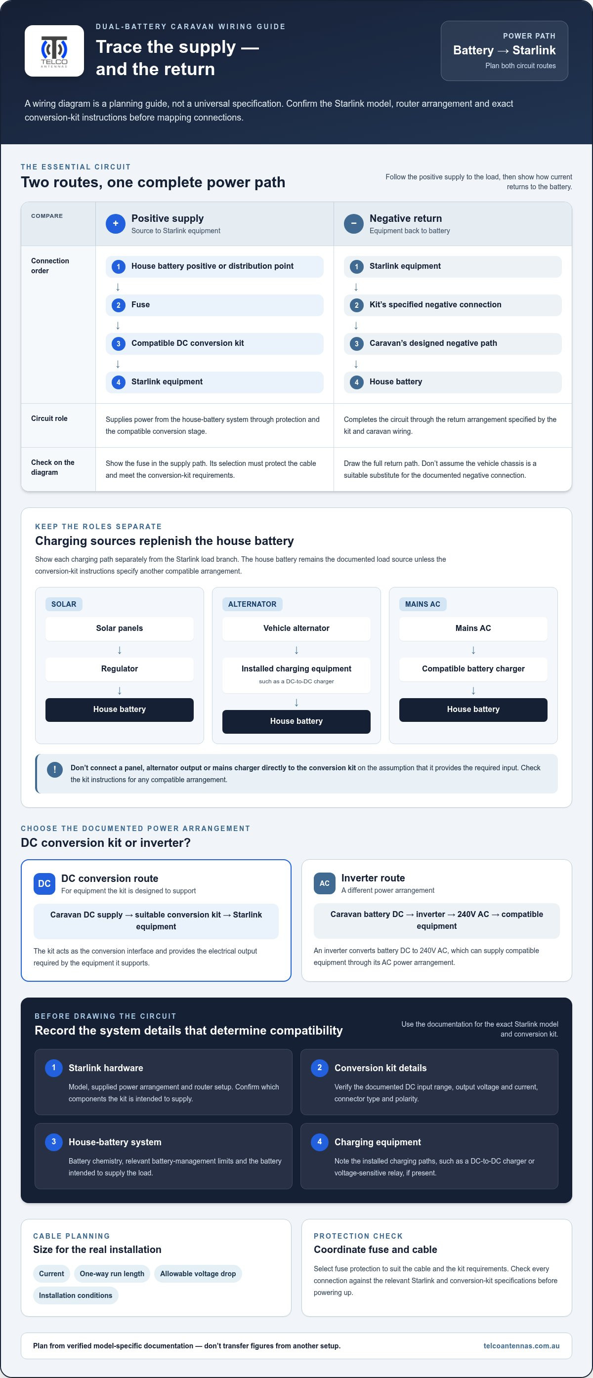
Think of the house battery as the source for the Starlink load and the charging equipment as the means of replenishing that battery. The load path is separate from the charging paths. Power flows from the house-battery positive connection through circuit protection and the compatible DC conversion kit to the Starlink equipment. Current then returns through the kit’s specified negative connection and the caravan’s negative path to the battery. Show both sides on the diagram.
A fused branch connects a load to the house-battery system. It takes positive supply from the battery or its distribution point through a fuse selected to protect the cable and meet the kit requirements, then routes it to the load. The negative connection returns through the system’s designed return path.
Draw the circuit as two clear routes, not just a positive wire running to the dish. The positive route shows the source, protection and conversion stage. The negative route shows the corresponding return from the Starlink equipment. The return arrangement depends on the caravan’s wiring and the kit instructions, so don’t assume the vehicle chassis is an appropriate substitute for a documented negative connection.
How do the house battery and charging sources fit together?
Charging equipment replenishes the house battery. It doesn’t automatically become a direct Starlink supply. Where fitted, show each charging path separately: solar panels through their regulator to the battery, alternator charging through the installed equipment, such as a DC-to-DC charger, and mains AC through a compatible battery charger. These components have different roles and shouldn’t be drawn as interchangeable load connections.
For example, a caravan may charge its house battery from solar while parked and from the vehicle alternator while travelling. In both cases, the battery remains the documented source for the Starlink branch unless the conversion kit instructions specify another compatible arrangement. Don’t connect a panel, alternator output or mains charger directly to the kit on the assumption that it provides the right input.
Why use a DC conversion path instead of an inverter?
A DC conversion route takes power from the caravan’s DC system through a suitable conversion kit to the Starlink equipment. An inverter route changes battery DC to 240V AC, which then supplies equipment through its specified AC power arrangement. The routes have different conversion stages, and the better choice depends on the hardware and installation.
An inverter can use power while operating and may draw standby power, but the amount depends on the particular inverter and its operating conditions. A DC conversion path has its own requirements too. Don’t assume a fixed efficiency gain or extra battery runtime without measurements for the equipment and setup involved.
A starlink dc power kit wiring diagram for dual battery caravan systems should show the battery-to-load route separately from every charging route, with the negative return mapped as carefully as the positive supply. Telco Antennas supplies Starlink aftermarket power conversion for installations planned around the caravan’s DC system.
Starlink DC power kit wiring diagram: connections in order
The diagram below shows the functional path, not a universal wiring specification. It follows the supply from the caravan’s house battery to the Starlink equipment and includes the negative return. A real installation must match the exact conversion kit instructions and the caravan’s electrical layout. Connector type, polarity, cable size and electrical ratings depend on the equipment being installed.
Positive supply: House battery positive → branch fuse near the supply source → any documented switch or connector → DC kit input positive → DC kit output → compatible Starlink connection.
Negative return: Starlink return → DC kit output return → DC kit input negative → the appropriate negative bus or battery connection shown in the kit and caravan system documentation.
How should the wiring diagram be read from source to load?
Read the positive path in order, starting at the house-battery positive terminal. The branch fuse is shown close to the supply source as a design point, but its rating and installation must be selected for the cable and kit requirements. Continue through an intermediate switch or connector only if it is part of the documented installation, then show the kit input and its Starlink output.
Next, trace the negative return in the opposite direction, from the Starlink equipment through the kit to the appropriate system connection. The return may connect to a negative bus or another point specified for the caravan and kit. Don’t add a chassis connection, switch or other component just because it appears in a different diagram.
Which diagram details must remain kit-specific?
Separate the layout from the values. The layout describes what connects to what; the values describe how that particular installation must be built. Use the exact kit and Starlink documentation to record the fuse rating, cable size, connector, polarity, input and output limits, and any other stated electrical requirements. If a detail isn’t verified, mark it as requiring confirmation rather than filling in a guess.
For example, don’t copy a connector, voltage or fuse value from a diagram intended for a Mini or Gen 3 setup into a different or unidentified installation. Similar-looking plugs don’t establish electrical compatibility. Wire colour isn’t a reliable substitute for labelling function either. Identify each conductor as positive supply, negative return or a specified output according to the kit documentation.
Use this connection order as a planning check before drawing a final installation diagram:
- Mark the house-battery positive and the intended negative return point.
- Place the documented branch protection on the positive supply path near its source.
- Show only the switches, connectors and conversion stages present in that installation.
- Label kit input and output by function, then verify polarity and ratings from the relevant documents.
This starlink dc power kit wiring diagram for dual battery caravan systems is illustrative. It clarifies the connection sequence, but it doesn’t replace the exact kit instructions, verified component values or an assessment of the installed caravan system.
Cable sizing, battery protection and faults to check before powering up
A circuit can be connected in the right order and still behave poorly if the cable run is too long or undersized for its load. In a caravan’s low-voltage DC system, cable resistance can reduce the voltage reaching the conversion kit. Voltage drop depends on current, one-way cable length, conductor size and material, and installation conditions such as routing and temperature.
How do cable length and voltage drop affect operation?
Use the kit’s documented input current and allowable voltage drop as inputs to a cable-size calculator, along with the full one-way distance from the supply point to the kit. Account for installation conditions and applicable requirements when choosing cable. Don’t select a cable size by copying a figure from another Starlink model or a shorter run. Both the load and circuit layout matter.
Check voltage at the kit input under operating conditions, not only at the battery terminals with the load disconnected. If the reading falls outside the kit’s documented input range, investigate the supply, cable path and connections before changing components.
What should be checked if Starlink does not start reliably?
Startup behaviour and acceptable input voltage are specific to the Starlink equipment and conversion kit. Battery voltage can also vary with state of charge, charging activity and battery-management limits. Compare measurements with the documentation for the exact setup, and consider whether the battery can support the load under the conditions when the fault occurs.
Before powering up, work through the checks in order. Isolate the supply before inspecting or altering wiring, and use appropriate measurement procedures for the system.
- Confirm positive and negative polarity at the battery branch, kit input and output connections.
- Check that terminals and connectors are secure, correctly seated and free from visible damage.
- Verify that the specified protective device is fitted, intact and appropriate for both the cable and kit requirements.
- Measure voltage at the kit input while the system is operating, then compare it with the documented limits.
- Check the kit’s status indications and follow its troubleshooting instructions before attributing the fault to the Starlink equipment.
A fuse isn’t selected by matching the appliance’s current alone. Its rating must coordinate with the cable’s current-carrying capacity and the conversion kit’s requirements, while protecting the cable from excessive current. Don’t fit a larger fuse to stop it opening without first identifying the cause and checking the cable and kit specifications.
Use the starlink dc power kit wiring diagram for dual battery caravan systems as a fault-finding map. It helps locate the supply, protection, conversion stage and return path so each can be checked methodically. For a planned installation, explore Starlink aftermarket power conversion as part of the caravan’s documented DC system.
Plan a compatible Starlink DC conversion for your caravan
A sound conversion plan starts with the specific equipment, then works outwards to the caravan’s electrical system. Starlink models, supplied power arrangements, conversion kits and battery installations can differ, so a diagram is useful only when it represents the hardware actually being connected. Establish compatibility by matching the relevant documentation, not by assuming similar-looking equipment shares the same requirements.
Use this decision sequence before settling on the circuit:
- Identify the Starlink model and the components its power arrangement needs to supply.
- Record the conversion kit’s documented input and output limits, connector and polarity.
- Document the house-battery source, battery-management limits and installed charging equipment.
- Map the positive supply, protection points, conversion path and negative return, then compare each detail with the relevant specifications.
This approach places aftermarket power conversion in its proper role: as a documented part of the battery-to-load path between a suitable caravan DC source and compatible Starlink equipment. It doesn’t make every battery system or Starlink setup interchangeable. If a model, kit or electrical detail changes, review the plan against the documentation rather than reusing the old diagram unchanged.
What information should the final wiring plan record?
Keep the finished diagram practical enough to use during installation and later fault-finding. Include the Starlink model, conversion kit, intended battery source, verified electrical limits, protection points and cable route. Label connectors, polarity and negative return by function, and record component-specific values only when they’ve been checked against the relevant documentation.
Store the diagram with the caravan’s equipment records and the instructions for its Starlink hardware and conversion kit. If the system is later altered, update the drawing so it still reflects the installed circuit.
How does Telco Antennas fit into a system-first approach?
Telco Antennas supplies Starlink aftermarket power conversion. Treat the conversion as one part of a model-appropriate installation plan, with the battery source, circuit layout and kit requirements considered together. For broader context on Starlink equipment and accessories, the Starlink accessories guide covers related options.
With the wiring guidance in place, explore Starlink aftermarket power conversion as part of planning your caravan’s DC system. A starlink dc power kit wiring diagram for dual battery caravan systems is most useful when it records verified details for your specific setup, not generic values copied from another installation.
Make your wiring plan the starting point
Keep the wiring plan with the caravan’s electrical records so it’s available if equipment changes or a fault needs diagnosing. Treat it as a live record: update it when you alter the battery arrangement, cable route or Starlink components, and recheck the relevant specifications before reconnecting the system. This makes the starlink dc power kit wiring diagram for dual battery caravan systems useful beyond installation day, helping you trace the circuit with the actual setup in front of you.
A carefully matched conversion is part of a broader system decision, not a one-size-fits-all wiring recipe. Telco Antennas supplies Starlink aftermarket power conversion to customers nationally across Australia.
Once you’ve identified the equipment and documented the circuit, explore Starlink aftermarket power conversion from Telco Antennas for your caravan DC system.
Frequently Asked Questions
Can I connect a Starlink DC power kit directly to my caravan battery?
Only connect it directly if the conversion kit is documented for the battery’s voltage range and the specific Starlink equipment. Battery voltage can vary with charging and state of charge, so a nominal system label alone doesn’t establish compatibility. In a starlink dc power kit wiring diagram for dual battery caravan systems, show the kit’s specified supply and protection rather than treating the battery terminals as a universal plug-in point.
Do I need an inverter to run Starlink from a dual-battery system?
No, not if the Starlink setup is supplied through a compatible DC conversion kit that accepts the caravan’s DC supply. An inverter is relevant when the chosen power arrangement requires 240V AC, but that adds an AC stage between the battery and equipment. Check whether the Starlink system’s supplied power components are designed for AC or whether the exact conversion kit provides a documented DC route.
How do I choose the correct fuse and cable size for a Starlink DC kit?
Use the kit’s specified current and protection requirements, then size the cable for that current, the one-way run length, allowable voltage drop and installation conditions. The fuse must protect the cable and meet the kit’s requirements, so don’t select it solely to match the Starlink load or prevent nuisance operation. If the route changes, recalculate rather than reusing a fuse and cable choice from a shorter installation.
Can solar charging run at the same time as Starlink on a caravan battery?
Yes, if the solar system is configured to charge the house battery and the battery system can support the load while receiving charge. The battery acts as the shared energy store, while solar output can vary with conditions such as shade or cloud. The solar regulator manages charging. Don’t treat panel output as a direct Starlink supply unless the equipment documentation specifically allows that arrangement.
What happens if the battery voltage drops while Starlink is starting?
If voltage at the conversion kit falls outside its documented input limits during startup, the equipment may fail to start, reset or operate intermittently. A battery reading taken before startup may not reveal a brief drop under load. Measure at the kit input during the event, then consider battery state, cable length, connection resistance and any battery-management cutoff before concluding that the Starlink hardware is faulty.
Can a Starlink DC conversion kit work with different Starlink models?
Not necessarily. Compatibility depends on the exact Starlink model, its power arrangement and the conversion kit’s documented input, output, connector and polarity. A connector that fits is not proof that the electrical requirements match. Don’t assume a kit described for one dish model will also suit a different model or router arrangement. Use the relevant documentation for the complete setup.
Should Starlink draw power from the starter battery or the house battery?
Usually, use the house battery, which is intended to supply caravan loads, rather than risking discharge of the starter battery needed to start the vehicle. A dedicated, correctly protected house-battery circuit also makes the load easier to account for when planning off-grid use. If the caravan has a specifically designed arrangement that supplies this load differently, follow its wiring and battery-management documentation rather than bypassing the intended isolation.


