
Selecting a standard RG58 cable for a high-frequency 5G or Starlink installation in the harsh Australian sun isn't just a budget choice; it's a guaranteed path to system failure. In RF engineering, your system is only as strong as its weakest link. Choosing a generic coaxial cable for modern, high-bandwidth signals is the fastest way to ensure your hardware never reaches its potential. You've likely experienced the frustration of a signal that's strong at the antenna but disappears before it reaches the modem, often due to high attenuation over long cable runs.
We understand that navigating the technical jargon of shielding effectiveness and velocity of propagation can be daunting. This guide provides the professional clarity required to eliminate signal loss and optimise your RF infrastructure. By examining the precise lmr-400 cable specifications, including its 50 Ohm impedance and 85% velocity of propagation, you'll learn why certain cables are non-negotiable for professional-grade deployments. We'll compare these metrics against common alternatives and detail how to select the right jacket materials to survive local conditions. This analysis ensures you can identify the correct cabling for 4G, 5G, and Starlink applications, ultimately reducing loss and securing a reliable connection for your specific setup.
Key Takeaways
- Understand the mechanical design of coaxial cables and why specific shielding geometry is essential for preventing signal leakage and external interference.
- Learn how to manage signal attenuation across different frequencies, ensuring your 5G or Starlink setup maintains high throughput over longer distances.
- Identify the specific material requirements, such as UV-stabilised polyethylene jackets, necessary to protect your RF infrastructure from the intense Australian sun.
- Review the lmr-400 cable specifications to see how this industry standard provides superior low-loss performance compared to traditional RG-series alternatives.
- Gain the technical expertise to select the correct cable and conductor materials for MIMO antennas and mobile signal boosters to maximise system reliability.
What is Coaxial Cable and Why is it Critical for RF Systems?
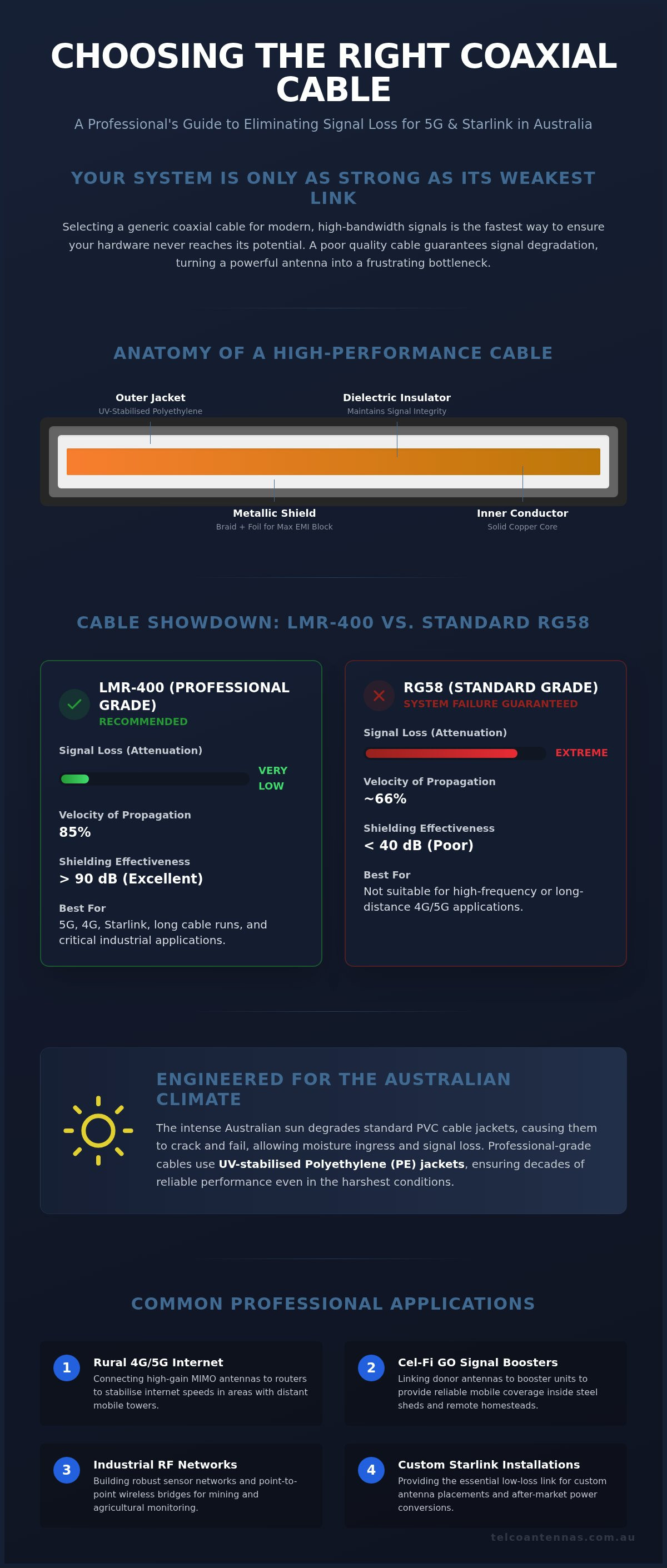
A coaxial cable is a specialised transmission line designed to carry high-frequency electrical signals with minimal loss. While standard copper wiring is sufficient for low-frequency power delivery, it's entirely unsuitable for moving radio waves. Coax consists of four concentric layers: an inner conductor, a dielectric insulator, a metallic shield, and an outer protective jacket. The term "coaxial" describes the shared geometric axis between the inner conductor and the outer shield. This specific physical arrangement allows the cable to function as a self-contained electromagnetic environment, keeping the signal trapped inside while blocking external noise.
The primary role of this cable is the efficient transport of Radio Frequency (RF) energy. In a typical Australian telecommunications setup, it moves data from an antenna to a receiver or modem. If the cable is poor quality or incorrectly specified, the signal often degrades or disappears before it reaches your hardware. When you examine lmr-400 cable specifications, you're looking at the engineering tolerances of this closed system and its ability to maintain signal strength over distance.
The Fundamental Purpose of a Coax Cable
High-frequency applications like 4G and 5G are incredibly sensitive to their surroundings. External electromagnetic interference (EMI) from power lines, motors, or other electronics can easily corrupt weak radio waves. Coax acts as a shielded vault for these signals. By maintaining a consistent distance between the centre conductor and the shield, the cable ensures that the electromagnetic field remains stable. This is why the precise lmr-400 cable specifications are so critical; any deviation in the dielectric or shield can lead to impedance mismatches and significant signal reflection.
Maintaining signal integrity is the difference between a high-speed link and a dropped connection. Coax provides a "closed system" where the radio waves don't radiate outward, and external signals can't get in. This allows for clean, high-bandwidth data transfers even in environments crowded with other electronic devices. It's the non-negotiable foundation for any professional RF installation.
Common Applications in Australian Telecommunications
In Australia, coax is the backbone of remote and industrial connectivity. We use it to bridge the gap between high-gain antennas and the sensitive electronics that process the signal. Common deployments include:
- Connecting MIMO antennas to 4G/5G routers in rural areas to stabilise internet speeds where towers are far away.
- Linking Cel-Fi GO boosters to external donor antennas to provide reliable mobile coverage inside steel sheds or remote homesteads.
- Building industrial RF sensor networks and point-to-point wireless bridges for mining and agricultural monitoring.
- Providing the necessary link for Starlink after-market power conversions and custom antenna placements.
In each of these scenarios, the choice of cable determines the final performance of the entire system. Using the right coax ensures that the expensive hardware you've installed actually receives the signal it needs to operate.
The Anatomy of a High-Performance Coax Cable
High-performance cables aren't merely thick wires; they're precision-engineered waveguides where every millimetre of construction dictates the final signal quality. To understand why lmr-400 cable specifications are the industry benchmark, we must examine the four concentric layers that form the cable's architecture. The centre conductor carries the primary signal, while the dielectric maintains the critical geometry required for stable impedance. Surrounding these is the metallic shield, which is protected by an outer jacket designed for physical resilience and environmental protection.
Conductors and Shielding: The Defence Against Interference
The centre conductor is the core path for RF energy. Professional cables typically utilise either solid copper or copper-clad aluminium (CCA). While CCA is lighter and often more cost-effective for long runs, solid copper provides superior conductivity for DC power, which is essential when using equipment like active signal boosters or remote-powered masthead amplifiers. Because of the skin effect, high-frequency signals travel almost exclusively on the outer surface of the conductor, making the quality and material of that surface paramount to reducing resistive loss.
Effective shielding requires a sophisticated, multi-layered approach to block external noise. LMR-400 employs a combination of 100% coverage aluminium foil bonded to the dielectric and a high-density tinned copper braid. The foil acts as a barrier against high-frequency interference, while the braid provides mechanical strength and handles lower-frequency electromagnetic noise. This dual-shielding architecture is why these cables achieve a shielding effectiveness of over 90 dB, ensuring the signal remains pure from the antenna to the receiver.
Dielectric Materials and Signal Velocity
The dielectric layer is far more than just an insulator; it's the component that defines the cable's characteristic impedance, which is standardised at 50 Ohms for Australian telecommunications. Most high-performance cables use a gas-injected, closed-cell foam polyethylene (PE). This foam is preferred over solid PE because it introduces more air into the structure, which reduces signal absorption and significantly increases the Velocity of Propagation (VoP).
According to official lmr-400 cable specifications, the VoP is approximately 85%, meaning the signal travels at 85% of the speed of light. A higher VoP is critical for time-sensitive data streams, such as those found in 5G networks and Starlink satellite systems, as it reduces phase shift and timing errors. If you're designing a system that requires maximum throughput, selecting high-quality low-loss cabling ensures these physical properties remain consistent over the entire length of the installation. The final layer, the outer jacket, is typically made of UV-stabilised Polyethylene to prevent moisture ingress and survive decades of exposure to the intense Australian sun.
Understanding Signal Loss (Attenuation) and Impedance
Attenuation is the unavoidable reduction in signal strength as RF energy travels through a cable. Measured in decibels (dB) per metre, it represents the energy converted into heat due to resistance and dielectric absorption. A critical rule of thumb for any technician is the 3dB principle: a 3dB loss in your cable run equates to losing exactly 50% of your signal power. If your antenna captures 10 watts of power but your cable setup has a 3dB loss, only 5 watts actually reaches your router. This logarithmic scale means that even small increases in dB loss result in massive drops in usable performance.
Higher frequencies, such as those used in 5G (3.5GHz) or Starlink (10-14GHz), suffer significantly more attenuation than lower 4G or telemetry bands. For instance, when reviewing lmr-400 cable specifications, the attenuation at 900 MHz is approximately 12.8 dB per 100 metres, but this climbs to roughly 22.2 dB at 2500 MHz. This exponential increase is why choosing a low-loss cable becomes a non-negotiable requirement as frequencies rise. Without the correct cable, the high-speed potential of a 5G installation is effectively choked before the signal enters the building.
Factors That Increase Signal Attenuation
Cable length is the most manageable variable in any installation. Shorter runs are always preferable because every additional metre introduces more surface area for resistance. Beyond length, the correlation between frequency and resistance is absolute; higher MHz signals have shorter wavelengths that interact more intensely with the cable's physical structure. Finally, connector quality plays a pivotal role. Poorly terminated connectors or those not rated for the specific frequency create impedance discontinuities. This leads to Voltage Standing Wave Ratio (VSWR) issues, where signal energy reflects back toward the source rather than reaching the antenna, further increasing total system loss.
The Impedance Rule: Why You Can’t Mix Cables
Telecommunications equipment is designed for a characteristic impedance of 50 Ohms. In contrast, domestic TV and satellite systems typically use 75 Ohm cabling, such as RG6. Connecting a 75 Ohm cable to a 50 Ohm mobile booster is a technical disaster. This 25 Ohm difference creates a massive impedance mismatch, forcing a significant portion of the RF energy to reflect back into the sensitive amplifier of the booster or modem. This can cause the hardware to overheat or even suffer permanent circuit failure. It's a mistake that can't be fixed with software or settings; it's a fundamental hardware incompatibility.
To identify the correct cable in the field, use this simple checklist:
- Check the jacket printing for professional 50 Ohm designations like LMR-400, RG-58, or RG-213.
- Inspect the connectors; 50 Ohm N-type or SMA connectors are the standard for telco gear, whereas 75 Ohm systems often use F-type threaded connectors.
- Observe the centre conductor; 50 Ohm cables generally have a thicker centre conductor relative to the overall dielectric diameter compared to 75 Ohm variants.
Always verify the lmr-400 cable specifications provided by the manufacturer before finalising a high-stakes installation. Ensuring an impedance match across every component is the only way to protect your equipment and guarantee the signal reaches its destination.
Selecting the Right Coax for Australian Environments
The Australian environment is uniquely hostile to RF infrastructure. High UV indices and extreme thermal cycling can degrade standard cable jackets in months rather than years. Cheap imported cables often utilise low-grade PVC jackets that become brittle and crack under the intense sun. This allows moisture to reach the braid and dielectric, leading to "black wire" corrosion and a total loss of signal integrity. Professional installations require UV-stabilised Polyethylene (PE) jackets. According to the lmr-400 cable specifications, these jackets are designed for a 20-year outdoor service life, providing the long-term reliability required for remote sites and homesteads.
Moisture ingress is the primary cause of system failure in coastal or tropical regions. Even a microscopic amount of water in the dielectric will significantly increase attenuation. Technicians must use waterproof N-type connectors and high-quality adhesive-lined heat-shrink to seal every outdoor join. For deployments where cables are run through trenches, LMR-400-DB (Direct Burial) variants should be used. These include a waterproofing compound inside the braid that prevents moisture from travelling down the length of the cable if the jacket is accidentally nicked during installation.
If you are planning a high-stakes deployment in a remote area, you can source professional-grade LMR-400 cables that are pre-terminated and tested for local conditions.
RG-58 vs. LMR-240 vs. LMR-400: Which One?
RG-58 is often found in basic vehicle setups, but its high loss makes it unsuitable for anything beyond a two-metre patch lead. LMR-240 serves as a functional middle ground. It offers a tighter bend radius for internal routing while maintaining better performance than RG-58. However, LMR-400 remains the industry gold standard for fixed wireless and Cel-Fi GO installations. It provides the lowest attenuation for building boosters, ensuring that the signal captured by a high-gain antenna isn't wasted before it reaches the electronics. When performance is the priority, the thicker diameter of LMR-400 is a necessary trade-off.
Fire Ratings and Indoor Compliance
Indoor installations bring additional regulatory requirements. Under the ACMA-mandated AS/CA S008:2020 and S009:2020 standards, cabling products must meet specific safety and interoperability criteria. For commercial buildings and multi-storey developments, fire-retardant (FR) or Low Smoke Zero Halogen (LSZH) variants are often mandatory. These jackets prevent the release of toxic fumes during a fire, which is a critical safety requirement for plenum spaces.
When routing these cables, technicians must maintain separation from electrical mains power to prevent inductive interference and comply with the "Wiring Rules". While the lmr-400 cable specifications indicate a semi-rigid structure, technicians should never exceed the minimum bend radius of 25.4 mm. Overtightening a cable around a corner can crush the dielectric foam, changing the impedance and causing signal reflections that degrade the entire network's throughput.
Professional RF Solutions: Why LMR-400 is the Industry Standard
In the context of modern Australian telecommunications, LMR-400 has emerged as the non-negotiable standard for high-performance RF installations. While standard RG-series cables like RG-58 were sufficient for legacy radio systems, they lack the shielding and low-loss characteristics required for high-frequency 4G and 5G signals. When comparing lmr-400 cable specifications against RG-213, the difference in attenuation is stark; LMR-400 offers roughly 40% less loss at 2.4 GHz. This performance gap ensures that the maximum possible signal strength reaches your hardware, which is critical in rural environments where every decibel counts toward maintaining a stable link.
Telco Antennas recommends the use of pre-terminated cables to eliminate the most common point of failure in any RF system: the connector interface. Field-crimped connectors often suffer from inconsistent pressure or improper stripping, leading to impedance mismatches and moisture ingress. By utilising factory-assembled leads, you ensure that every termination has been precision-crimped and tested for VSWR compliance. This approach significantly increases site reliability and reduces the likelihood of costly return visits to remote locations.
The Telco Antennas Approach to Cabling
Our engineering team focuses on the intersection of hardware performance and physical durability. We utilise high-quality N-Type and SMA connectors, ensuring each assembly is built to withstand the mechanical stresses of a professional installation. To reduce on-site labour, we organise cable assemblies with clear labelling and pre-fitted weatherproofing. This methodical preparation is supported by our capability to conduct RF site surveys, which allow us to determine the exact lmr-400 cable specifications and lengths required for a specific environment. This data-driven approach removes the guesswork from communication tower design and remote black spot remediation.
Optimising Your Setup with the Right Hardware
The performance of advanced hardware like Cel-Fi GO mobile boosters and high-gain MIMO antennas is directly tied to the quality of the coaxial link. A high-gain antenna's benefits are easily negated by using high-loss cabling. To ensure a no-compromise installation, follow this final technical checklist:
- Verify the cable impedance is exactly 50 Ohms.
- Ensure all outdoor connectors are sealed with adhesive-lined heat-shrink.
- Match the cable's attenuation rating to the expected frequency of the 4G/5G carrier.
- Confirm the bend radius does not exceed the manufacturer's limit of 25.4 mm.
By adhering to these engineering standards, you protect your investment and guarantee long-term network stability. If you require a custom solution for a complex industrial or remote site, you can enquire about our professional LMR-400 cable assemblies to ensure your system operates at peak efficiency.
Optimising Your RF Infrastructure for Long-Term Reliability
Achieving a high-performance wireless link requires more than just a powerful antenna; it demands a transmission path that respects the laws of physics. As we've detailed, selecting a cable based on verified lmr-400 cable specifications is the most effective way to combat signal attenuation and environmental degradation. By prioritising proper impedance matching and UV-resistant materials, you protect your hardware from the premature failures common in local conditions.
Telco Antennas has operated as a specialist in low-loss RF cabling since 2008, offering Australian-based technical support and precision engineering. We provide custom cable assemblies made to order, ensuring every connection is factory-tested for industrial reliability. When you're ready to eliminate signal dropouts and stabilise your data throughput, browse our range of high-performance LMR-400 coaxial cables. Investing in the right foundation today ensures your system remains operational for years to come.
Frequently Asked Questions
What is the difference between 50 Ohm and 75 Ohm coax cable?
The primary difference lies in the characteristic impedance, which dictates how the cable handles power and signal loss. 50 Ohm cables are the industry standard for two-way data and radio transmissions, including mobile boosters and wireless networks, because they offer a balance between power handling and low attenuation. 75 Ohm cables are typically used for receive-only applications like domestic TV and satellite systems, where signal loss is the main priority over power capacity.
Can I use standard TV coax for my 4G or 5G antenna?
No, you should never use standard 75 Ohm TV coax for cellular antennas. Most 4G and 5G hardware is designed for 50 Ohm impedance; connecting it to a 75 Ohm cable creates a significant impedance mismatch. This mismatch causes radio frequency energy to reflect back into your equipment, which leads to reduced data speeds, increased noise, and potential damage to the sensitive amplifiers inside your router or signal booster.
How much signal loss does a 10-metre coax cable have?
Signal loss depends on the cable type and the frequency of the signal being transmitted. For a 10-metre run at 2500 MHz, a high-quality LMR-400 cable loses approximately 2.2 dB of signal strength. In contrast, a thinner RG-58 cable would lose over 7 dB in the same scenario, which equates to losing more than 80% of your signal power. Checking the lmr-400 cable specifications is essential for calculating an accurate link budget.
What is the best coax cable for a long-distance antenna run?
LMR-400 is widely considered the best low-loss cable for fixed wireless runs between 10 and 30 metres. If your installation requires a run exceeding 30 metres, you may need to step up to even thicker cables like LMR-600 to keep attenuation within acceptable limits. For very long industrial runs, professional installers often use corrugated hardline copper cables, though these are much less flexible and more expensive than standard LMR-series options.
Does the thickness of a coax cable affect signal quality?
Yes, the physical thickness of a cable is directly related to its performance and signal integrity. A larger diameter allows for a thicker centre conductor and a more robust dielectric layer, which significantly reduces electrical resistance and signal attenuation over distance. While thicker cables like LMR-400 are harder to route due to their larger bend radius, they are necessary for high-frequency applications where preserving every decibel of signal strength is critical for system performance.
What are the most common connectors used with coax cables in Australia?
N-Type connectors are the most common choice for outdoor antennas and industrial RF equipment due to their rugged, weatherproof design. For internal connections to routers and mobile boosters, SMA or RP-SMA connectors are the standard. While you may occasionally encounter TNC or BNC connectors on legacy radio gear, most modern Australian 4G, 5G, and Starlink after-market installations rely on N-Type and SMA interfaces to ensure a secure, low-loss connection.
Is LMR-400 cable worth the extra cost over RG-58?
LMR-400 is definitely worth the investment for any fixed installation where data speed and connection stability are priorities. Because the lmr-400 cable specifications confirm much lower attenuation than RG-58, you'll retain significantly more signal power over the same distance. For a typical 10-metre run, the performance difference is often the deciding factor between a high-speed 5G connection and a system that constantly drops out due to insufficient signal levels.
How do I protect my coax cable connectors from the weather?
The most effective way to protect outdoor connectors is to seal them with adhesive-lined heat-shrink tubing or self-amalgamating rubber tape. Standard electrical tape isn't sufficient for the harsh Australian climate and will eventually peel, allowing moisture to enter the connector. If water reaches the internal pins or the cable's dielectric, it will cause rapid corrosion and signal degradation, often requiring the entire cable assembly to be replaced to restore system performance.


