
In the world of RF engineering, the most sophisticated 5G antenna or Starlink terminal is only as capable as the coaxial cable connecting it to your hardware. It's a hard truth that many high-gain systems fail to deliver their theoretical performance simply because the transmission line wasn't up to the task. You've likely felt the frustration of signal attenuation at high frequencies, especially when trying to decipher the practical differences between legacy RG58 and modern LMR-400 standards while facing the reality of cheap jackets failing under the harsh Australian sun.
We agree that selecting the right hardware shouldn't feel like a guessing game. This guide provides the technical clarity you need to master cable selection, allowing you to eliminate signal loss and maximise your RF system performance. We'll examine the physics of signal loss in decibels, explain how to choose the correct cable for 4G or 5G applications, and verify which connectors provide the most reliable mechanical interface. By the end of this article, you'll have the expertise to specify a system that survives extreme UV conditions while maintaining peak signal integrity.
Key Takeaways
- Identify the fundamental mechanical differences between 50 Ohm telecommunications systems and 75 Ohm television setups to prevent critical impedance mismatches.
- Understand how internal material selection, such as gas-injected foam dielectrics, directly impacts signal attenuation at higher frequencies.
- Learn to navigate naming conventions to choose the optimal LMR-series coaxial cable for modern 4G, 5G, or Starlink aftermarket integrations.
- Discover how to calculate a maximum allowable signal budget to ensure your RF system maintains peak performance across extended cable runs.
- Gain the knowledge to specify UV-stabilised components that are specifically engineered to survive the rigours of the Australian climate without material degradation.
Understanding Coaxial Cable: The Foundation of RF Systems
A Coaxial cable functions as a precision-engineered transmission line designed to guide radio frequency (RF) energy with minimal leakage. It consists of a central conductor surrounded by a dielectric insulator, which is then enclosed by a metallic shield and a protective outer jacket. The physical relationship between these components is what determines the cable's performance. It's a delicate balance of physics and material science.
Professional RF design begins with the principle of impedance matching. In simple terms, impedance is the total opposition a circuit offers to the flow of alternating current. If the impedance of your antenna, cable, and booster don't align, the signal won't flow efficiently. Instead, a portion of the energy reflects back toward the source. This creates Voltage Standing Wave Ratio (VSWR) issues that can degrade performance or even damage sensitive equipment. Matching these values is the first and most critical rule of any high-performance installation.
The 50 Ohm Standard in Australian Telecommunications
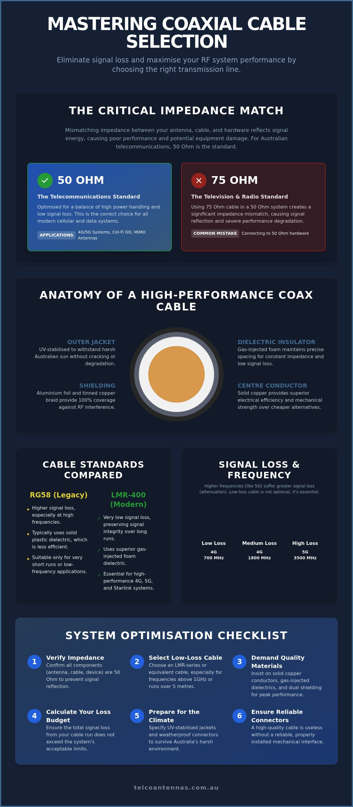
Most telecommunications hardware in Australia, including Cel-Fi GO boosters and MIMO antennas, is designed for a 50 Ohm system. This standard is specifically optimised for a balance between high power handling and low signal loss. You'll commonly find 50 Ohm ratings in cables like the legacy RG58 or the modern LMR series used for mobile data and industrial wireless applications.
A frequent mistake in DIY installations is using 75 Ohm coaxial cable, which is the standard for digital television and radio distribution. While 75 Ohm cable is excellent for those specific applications, using it in a 4G or 5G system creates a significant impedance mismatch. This mismatch causes signal reflections that can lead to dropped connections and reduced data speeds, effectively bottlenecking your hardware's potential before the signal even reaches the modem.
Frequency Response and Bandwidth Requirements
Cable performance isn't static; it changes based on the frequency of the signal passing through it. A cable that performs adequately at 700 MHz for rural 4G may suffer from extreme attenuation at 3500 MHz for mid-band 5G. This is largely due to the "skin effect," where high-frequency signals tend to travel only on the outer surface of the conductor rather than through its centre. This increases the effective resistance of the line as frequencies climb.
To combat this, high-performance cables require sophisticated construction. The dielectric insulator must maintain exact spacing between the conductors to keep impedance constant across the entire run. Modern low-loss cables often use gas-injected physical foam dielectrics. These provide better structural integrity and lower signal absorption than older, solid plastic designs, ensuring that more of your signal reaches its destination.
Anatomy of a High-Performance Coax Cable
While impedance matching provides the electrical foundation, the physical anatomy of a coaxial cable dictates how it performs under stress. High-performance cables are constructed from four distinct layers, each engineered to address specific technical challenges. The interaction between these materials determines the cable's velocity of propagation and its ability to resist external interference.
The centre conductor serves as the primary path for RF energy. While budget options often use copper-clad aluminium (CCA), professional-grade installations rely on solid copper. Aluminium is lighter but lacks the mechanical strength and electrical efficiency of copper. Surrounding this is the dielectric insulator. In modern low-loss cables, this is usually a gas-injected physical foam. This material is critical because it maintains the exact distance between the centre conductor and the shield. If this spacing varies, the impedance fluctuates, leading to the signal reflections that degrade system throughput.
Effective shielding requires a combination of aluminium foil and tinned copper braiding. The foil provides 100% coverage against high-frequency electromagnetic interference (EMI), while the braid adds structural strength and manages lower-frequency noise. Finally, the outer jacket must be UV-stabilised. Australian rooftops experience extreme thermal cycling and high UV indices. A standard indoor PVC jacket will crack within months, allowing moisture to ingress and ruin the cable's dielectric properties through oxidation.
Conductor Materials and Signal Integrity
Conductor diameter is a primary factor in signal loss; as the diameter increases, attenuation decreases. For highly sensitive applications, silver-plated copper is sometimes used to exploit silver's superior conductivity, though solid copper remains the industrial standard. We strongly advise against CCA in coastal environments. The junction between the aluminium core and copper cladding is highly susceptible to galvanic corrosion when moisture is present, leading to rapid signal degradation and mechanical failure at the connector interface.
Shielding Effectiveness and Interference Rejection
In environments with high RF density, such as urban rooftops or industrial sites, shielding effectiveness is paramount. Dual-shield cables using foil and braid are standard, but quad-shielding provides additional layers to prevent signal leakage. This is vital for maintaining a clean signal path and preventing your system from becoming a source of interference for others. Shield bonding, where the foil is chemically bonded to the dielectric, ensures the cable maintains its shielding integrity even when bent during a complex installation. If you require a high-reliability link, specifying a custom cable assembly ensures every component meets these rigorous mechanical standards.
RG vs. LMR: Comparing Industry-Standard Coaxial Cables
RG stands for "Radio Guide," a military specification dating back to World War II. While these cables were sufficient for analogue voice transmissions and early radio systems, they weren't designed for the high-frequency requirements of modern digital data. The LMR series evolved to meet these demands, offering significantly lower attenuation and superior shielding. In a modern RF environment, the choice between these standards isn't just about price; it's about whether your system will function at all. RG58 is the most common retail mistake. While it's flexible and inexpensive, it acts as a massive bottleneck in 4G and 5G systems. Because it lacks the high-grade dielectric found in LMR variants, it loses signal rapidly as frequencies climb.
Attenuation Comparison: dB Loss per 10 Metres
To understand the impact of cable choice, we must look at attenuation, measured in decibels (dB) of loss over a standard 10-metre run. It's helpful to remember the "3dB rule": every 3dB of loss represents a 50% reduction in signal power. This "invisible thief" can quickly negate the gains of a high-performance antenna. Consider the performance gap across common Australian frequencies:
- 700MHz (Rural 4G): RG58 loses approximately 4.5dB, while LMR-400 loses only 0.7dB.
- 1800MHz (Urban 4G): RG58 loses approximately 7.5dB, whereas LMR-400 maintains a low 1.2dB loss.
- 3500MHz (5G): RG58 bleeds a staggering 11dB, while LMR-400 remains efficient at 1.7dB.
The transition point is clear. While LMR-195 or LMR-240 might suffice for short jumpers under three metres, any installation exceeding that distance should move to LMR-400. Using a high-loss coaxial cable for a 10-metre run can result in losing over 90% of your signal power before it even reaches your device.
Mechanical Differences: Bend Radius and Flexibility
Performance often comes at the cost of flexibility. Solid-core LMR-400 is relatively stiff, with a minimum bend radius of approximately 25mm. Attempting to force a tighter turn can "kink" the internal foil or crush the foam dielectric, causing a permanent impedance mismatch. For mobile or marine installations where the cable must navigate tight cavities, "Ultraflex" variants are the correct choice. These use a stranded centre conductor and a thermoplastic rubber jacket to provide greater flexibility without the catastrophic loss of an RG-series cable. Weight is also a factor; for telescopic mast deployments, the cumulative load of heavy LMR-400 runs must be calculated against the mast's payload capacity to ensure structural safety and prevent the mast from bowing under the weight of the cable loom.
Selection Guide: Matching Cable to Your Application
Selecting the correct coaxial cable requires a calculation of your total signal budget. This budget is the difference between the raw signal captured by your antenna and the minimum input required by your receiver. If your antenna provides 10dBi of gain but your 15-metre cable run introduces 12dB of loss, your system is effectively worse than having no antenna at all. For modern sub-6GHz 5G applications, the tolerances are even tighter. High-frequency signals are more prone to absorption and scattering, making low-loss transmission lines essential for maintaining usable data throughput.
Distance-based rules of thumb are helpful for Australian residential and commercial sites. For short runs under 3 metres, such as internal patch leads, LMR-195 or LMR-240 is usually sufficient. However, for any external run between 5 and 20 metres, LMR-400 is the industrial benchmark. Beyond 20 metres, you must either move to LMR-600 or reconsider your equipment placement to shorten the cable path. Connector compatibility is equally vital. Most outdoor antennas use N-Type connectors for their robust, weather-resistant properties, while mobile boosters like the Cel-Fi GO often utilise SMA or TNC interfaces. Ensure your cable assemblies use impedance-matched connectors to avoid the signal reflections discussed in previous sections.
Cabling for Mobile Signal Boosters (Cel-Fi GO)
For Cel-Fi GO installations, LMR-400 is the non-negotiable standard for the donor antenna run. Because these boosters operate at high gain, using a poorly shielded cable can lead to internal interference or oscillation. This occurs when the boosted signal leaks back into the donor antenna, causing the system to reduce power to protect the network. High-grade shielding in LMR-400 prevents this leakage, ensuring the booster can operate at its maximum 100dB gain. Weatherproofing is the final critical step. In the Australian climate, all external connections should be sealed with self-amalgamating tape followed by a layer of UV-rated electrical tape to prevent moisture ingress into the connector body.
Specialised Applications: Starlink and Point-to-Point
Modern Starlink aftermarket power conversions and Point-to-Point wireless bridges also demand high-specification cabling. When converting Starlink systems for DC operation in caravans or remote sites, the coaxial cable must handle both the RF signal and the power requirements of the dish. This necessitates a cable with a substantial centre conductor to minimise voltage drop. For wireless bridges, low-loss coax ensures that the link maintains the highest possible modulation rates for maximum bandwidth. Signal velocity factor is the ratio of the speed at which a signal travels through a cable compared to the speed of light in a vacuum, a critical metric for timing-sensitive digital data. If you are unsure which specification fits your specific site layout, our team provides expert RF site surveys to ensure your hardware is supported by the correct infrastructure.
The Telco Antennas Advantage: Engineering-Grade Connectivity
At Telco Antennas, we recognise that a high-performance coaxial cable is a critical component of a functional RF system. Since 2008, our in-house engineering team has specialised in providing the infrastructure required to support remote Australian sites. Unlike traditional retail outlets, we don't just supply hardware; we provide engineering-grade solutions designed for real-world reliability. This starts with our commitment to supplying genuine, high-specification LMR-400 cable, which remains the cornerstone of our Cel-Fi GO and MIMO antenna installations.
We provide custom-terminated cable assemblies to facilitate rapid site deployment. By terminating and testing cables in a controlled environment before they reach the field, we eliminate the risks associated with poor on-site crimping or connector contamination. These assemblies are integral to our larger infrastructure projects, including our telescopic mast trailers and aluminium tri-pods, where precise cable management is essential for long-term mechanical safety. Every assembly is built to withstand the rigours of industrial use, ensuring that your transmission line doesn't become the weak link in your communication chain.
Why We Recommend LMR-400 for Most Australian Installs
We recommend LMR-400 for the majority of Australian installations because it offers the optimal balance between cost-efficiency and ultra-low attenuation. It provides the thermal stability required for our climate, maintaining its physical properties even during extreme heat cycles. In our experience, upgrading from standard retail-grade cable to genuine LMR-400 is often the single most effective way to solve persistent "black spot" coverage issues. One industrial client reported a 15dB improvement in signal strength simply by replacing a degraded 20-metre run of generic coax with our UV-stabilised LMR-400, effectively moving their system from a non-functional state to peak performance.
Expert Support for Complex RF Infrastructure
Our consultative approach extends to communication tower design and comprehensive RF site surveys. We ensure every component of your signal chain, from the donor antenna to the modem interface, is mathematically optimised for your specific environment. This methodical process ensures that theoretical gains are actually realised in the field. If you are managing a complex installation or require a bespoke transmission line, contact our engineering team for a custom RF solution. We act as a dependable partner, providing the technical expertise necessary to bridge the gap between complex engineering and practical application.
Optimising Your RF Infrastructure for Long-Term Performance
Achieving a reliable high-performance wireless link requires more than just a high-gain antenna; it demands a transmission line that respects the physics of signal propagation. By prioritising 50 Ohm impedance matching and selecting low-loss LMR-series hardware, you eliminate the bottlenecks that often plague residential and industrial sites. It's vital to remember that the Australian sun remains a primary factor in material degradation, so specifying UV-stabilised jackets is essential for any external run. The correct coaxial cable doesn't just connect your components; it preserves the integrity of your data throughput across the entire signal chain.
Since 2008, Telco Antennas has acted as a technical partner for remote and industrial projects, specialising in industry-standard Cel-Fi and LMR hardware. We provide national delivery to ensure your site has access to engineering-grade components regardless of location. Our engineering team is focused on ensuring your equipment functions correctly through a lens of seasoned experience. Browse our range of high-performance coaxial cables and connectors to find the mechanical solution for your next project. With the right infrastructure in place, you can be certain your RF system is built for long-term success.
Frequently Asked Questions
What is the difference between RG58 and LMR400 coaxial cable?
RG58 is a legacy 5mm diameter cable originally designed for basic radio needs, whereas LMR400 is a 10mm high-performance standard. The primary difference lies in the dielectric material and conductor size. LMR400 utilises a much larger centre conductor and gas-injected foam to achieve significantly lower attenuation. While RG58 is more flexible for internal routing, its high loss makes it unsuitable for any run exceeding a couple of metres in modern systems.
How much signal loss should I expect over a 20-metre cable run?
Signal loss depends entirely on your operating frequency and the cable grade. Over a 20-metre run of LMR400, you can expect a loss of approximately 1.4dB at 700MHz and roughly 3.4dB at 3500MHz. If you were to use a thinner cable like RG58, those figures would climb to over 9dB and 22dB respectively. This demonstrates why choosing a high-quality coaxial cable is vital for maintaining a usable signal budget over distance.
Can I use standard TV coaxial cable for my 4G mobile booster?
No, you cannot use TV cable for telecommunications hardware. Digital television systems operate on a 75 Ohm standard, while 4G and 5G equipment is engineered for a 50 Ohm impedance. Mixing these creates a mismatch that causes signal reflections, known as a high VSWR. This results in poor data throughput and can potentially cause your booster to shut down to protect its internal circuitry from reflected power.
What does "low-loss" actually mean in coaxial cable terminology?
"Low-loss" refers to a cable's ability to transport RF energy with minimal heat dissipation or leakage. This is achieved through a combination of a larger centre conductor, a high-efficiency foam dielectric, and dual-layer shielding. In practical terms, a low-loss coaxial cable preserves more of the original signal captured by the antenna, ensuring that your modem or booster receives a clean, high-amplitude signal rather than one buried in noise.
How do I choose the correct connectors for my coaxial cable?
Start by identifying the interface on your hardware, which is typically N-Type for outdoor antennas and SMA for internal boosters. You must then ensure the connector is sized correctly for your specific cable diameter, such as a 10mm connector for LMR400. Always use high-quality, 50 Ohm crimp or clamp connectors. It's essential that the connector maintains the cable's internal geometry to prevent impedance bumps at the connection point.
Does the thickness of a coaxial cable affect its performance?
Yes, cable thickness is a primary indicator of performance. A thicker cable allows for a larger centre conductor, which reduces electrical resistance and skin effect losses. It also provides more space for a robust dielectric layer, which is critical for maintaining consistent impedance. While thinner cables are easier to install in tight spaces, they'll always exhibit higher attenuation than their thicker counterparts over the same distance and frequency.
Is it better to have a shorter cable or a higher-gain antenna?
It's almost always better to prioritise a shorter cable run. While a higher-gain antenna increases the raw signal, a long or poor-quality cable can quickly bleed that gain away while increasing the noise floor. Minimising the distance between your antenna and your hardware preserves the signal-to-noise ratio (SNR). If a long run is unavoidable, the only solution is to use a premium, ultra-low-loss cable to protect the antenna's performance.
What happens if I bend my coaxial cable too sharply?
Bending a cable beyond its specified minimum radius can permanently damage the internal structure. This "kinking" crushes the foam dielectric, which changes the precise spacing between the centre conductor and the shield. This deformation creates an impedance mismatch at the bend, causing signal reflections back toward the source. In extreme cases, the internal foil shield can crack, leading to signal leakage and exposure to external electromagnetic interference.


