
If you can see the distant antenna with your own eyes, the link should be perfect, right? In the world of professional RF engineering, visual line-of-sight is often a deceptive metric that leads to underperforming networks. You've likely experienced the frustration of a point-to-point link that looks flawless through binoculars but suffers from intermittent signal dropouts or poor data throughput. This typically occurs because the critical 3D space surrounding the direct signal path, known as the fresnel zone clearance, is being encroached upon by the terrain, vegetation, or man-made structures.
We recognise that achieving stable, high-speed connectivity across the Australian landscape requires a methodical approach to spatial physics rather than guesswork. This guide will help you master the technical requirements of Fresnel zone clearance to ensure your wireless links deliver maximum throughput without the nuisance of signal dropouts. We'll examine the specific formulas for calculating mast heights, explain how to account for the earth's curvature on links exceeding 15km, and detail the strategies needed to eliminate multipath interference in complex environments.
Key Takeaways
- Understand the critical distinction between visual line-of-sight and radio frequency line-of-sight to identify why clear views don't always guarantee a stable connection.
- Learn why maintaining a minimum of 60% fresnel zone clearance is the essential engineering standard for preventing phase cancellation and signal dropouts.
- Discover how to account for specific Australian environmental variables, including the "Earth Bulge" effect on long-distance links and the RF absorption properties of native vegetation.
- Master the fundamental calculations required to determine the necessary height for masts and tri-pods based on link distance and operating frequency.
- Recognise when to utilise professional RF site surveys and software modelling from specialists like QuantSec to ensure link reliability in complex terrain before investing in hardware.
Understanding the Fresnel Zone and RF Line-of-Sight
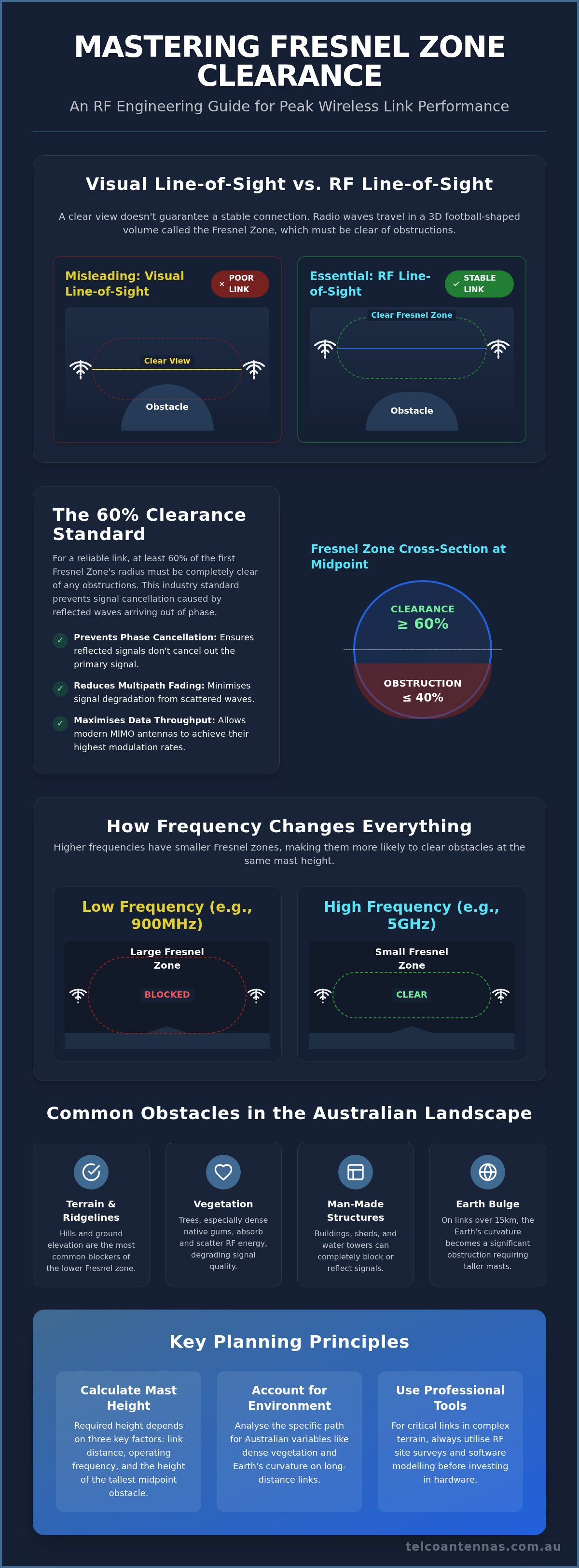
Achieving a stable wireless link requires more than just pointing two antennas at each other. While it's tempting to visualise radio waves as a narrow, laser-like beam, the reality of physics is significantly more complex. Radio frequency (RF) energy actually radiates in a three-dimensional, football-shaped volume known as a Fresnel Zone. This ellipsoidal region represents the space where the vast majority of your signal energy travels. Maintaining proper fresnel zone clearance is the single most important factor in determining whether your link delivers peak throughput or suffers from constant packet loss and latency spikes.
The Ellipsoid Shape: Why RF is Not a Straight Line
Radio waves don't simply move in a straight line; they diffract and reflect off every surface they encounter within the environment. This behaviour creates multiple concentric zones of interference. The most critical of these is the "First Fresnel Zone", as it contains the primary concentration of signal energy. Because of the way electromagnetic waves propagate through the atmosphere, this zone is narrowest at the antenna feed points and reaches its maximum diameter at the exact midpoint between the two sites. Essentially, the Fresnel zone is a dynamic volume of space required for wave propagation without phase cancellation, which occurs when reflected signals arrive at the receiving antenna out of sync with the direct signal.
Visual vs. Radio Line-of-Sight
There's a persistent misconception in the field that if you can see the distant tower with your own eyes, you have a clear path. This is merely visual line-of-sight (LoS). RF line-of-sight is far more demanding because it requires the entire first zone to be mostly unobstructed. Even if you have a clear view, an obstacle like a shed roof, a ridgeline, or even a dense treeline protruding into the lower half of the ellipsoid creates "near-line-of-sight" (nLoS) conditions. These obstructions cause signal scattering and multi-path interference that can cripple a high-speed data link.
Frequency is a critical variable in this equation. Higher frequencies, such as those in the 5GHz or 60GHz bands, have much smaller ellipsoids than lower frequencies like 900MHz. This means that while a 5GHz link might clear a particular obstacle, a 900MHz link mounted at the same height would likely fail due to insufficient fresnel zone clearance. When planning your installation, you must account for the specific frequency's spatial requirements to ensure the signal remains intact over long distances.
The Physics of Signal Interference: Why 60% Clearance is the Standard
Understanding the physics of wave propagation is essential for anyone installing a long-distance wireless bridge. When radio waves travel through space, they don't move as a single, isolated unit. Instead, the signal consists of multiple wavefronts. If these wavefronts encounter an obstacle, they reflect and scatter, arriving at the receiving antenna at slightly different times. This phenomenon, known as phase interference, is the primary reason why fresnel zone clearance is so critical. If a reflected wave arrives 180 degrees out of phase with the primary signal, the two waves effectively cancel each other out, leading to a complete loss of signal regardless of how much power your transmitter is pushing.
Many installers focus solely on the Received Signal Strength Indicator (RSSI), but this only tells half the story. You can have a strong RSSI and still experience a failing link if your Carrier to Interference plus Noise Ratio (CINR) is poor. Encroachment into the Fresnel zone degrades signal quality by introducing noise and phase errors. This is particularly damaging for modern MIMO antennas that rely on spatial multiplexing to achieve high data rates. If the spatial environment is cluttered by obstacles, the hardware cannot distinguish between the multiple data streams required for high-speed throughput, often forcing the link to downshift to a lower, less efficient modulation rate.
Constructive vs. Destructive Interference
The interaction between the direct signal and its reflections determines the stability of your connection. When reflections from the ground or bodies of water arrive in phase, they provide constructive interference, which can actually strengthen the signal. However, if a wave clips a physical obstacle, it undergoes a phase shift. These out-of-sync reflections cause "multipath fading", where the signal strength fluctuates rapidly. Even seemingly minor obstructions, such as a single power line or a thin branch, can introduce enough jitter to disrupt sensitive VoIP or video streaming traffic.
The 60% Rule and Link Reliability
In professional RF engineering, the Fresnel Zone clearance rule dictates that at least 60% of the first Fresnel zone must remain entirely free of obstructions. This 60% figure is considered the "sweet spot" because it ensures that any reflections occurring outside this radius will not arrive with enough phase-shift to cause significant destructive interference. Once blockage exceeds 40%, the link usually suffers from massive packet loss. In these marginal scenarios, using low-loss LMR-400 coaxial cables becomes vital to preserve what remains of the signal integrity before it reaches the wireless bridge, as every decibel of loss further reduces your fade margin.
Common Obstacles and Environmental Factors in Australia
Designing a point-to-point link in Australia requires a keen understanding of how our unique environment interacts with radio waves. While open plains might look like the ideal setting for long-distance connectivity, they often hide subtle variables that can degrade fresnel zone clearance over time. From the deceptive density of native vegetation to the literal curvature of the planet, professional installers must account for factors that aren't always present in standard technical manuals. Understanding these environmental stressors is the first step toward building a resilient network.
Australian flora is particularly challenging for RF propagation. Even "dry" looking scrub and eucalyptus trees contain significant moisture within their core, which acts as a highly effective absorber of RF energy. If your signal path grazes the canopy, the moisture in the leaves and branches will attenuate the signal, leading to packet loss. Man-made structures like corrugated iron sheds, grain silos, and power infrastructure also present significant risks. Metal surfaces are notorious for causing multipath interference, where reflections off a shed roof can bounce back into the primary signal path and cause phase cancellation.
The Earth Curvature Factor
On long-distance links exceeding 10 to 15 kilometres, the earth's curvature becomes a primary physical obstacle. This phenomenon, often called "Earth Bulge", means the surface of the planet effectively "rises" in the middle of your link path. For a 20km link, the earth bulges approximately 6 metres at the midpoint. When you combine this with the radius of the first Fresnel zone, you often find that standard roof mounts are insufficient. This is why telescopic mast trailers and heavy-duty skids are essential for outback deployments; they provide the necessary elevation to lift the link above the horizon and maintain a clear path.
Dynamic Obstacles: Growth and Weather
A link that functions perfectly today might fail in five years due to the "seasonal clearance" problem. When planning an installation near vegetation, you should always calculate for the expected height of trees in ten years rather than their current height. A fast-growing species can quickly encroach upon your fresnel zone clearance, turning a high-throughput link into a source of constant dropouts. Additionally, the extreme heat in many Australian regions can cause "thermal ducting". This occurs when temperature inversions in the atmosphere effectively bend the signal path, potentially pushing the Fresnel zone into the ground or other obstacles that were previously cleared. Using Aluminium Tri-pods or permanent masts with a high safety margin for height is the most pragmatic way to mitigate these environmental shifts.
How to Calculate and Optimise Fresnel Zone Clearance
Transitioning from theoretical physics to a functional installation requires a precise set of calculations. While software modelling provides the most accurate results, understanding the manual steps involved allows a technician to make informed adjustments on-site. To ensure your link operates at its maximum potential, you must follow a methodical sequence that accounts for both the signal's behaviour and the physical constraints of the Australian landscape.
The following steps outline the professional process for determining required antenna elevation:
- Step 1: Establish the total link distance in kilometres and the specific operating frequency in GHz (e.g., 5.8 GHz).
- Step 2: Calculate the radius of the first Fresnel zone at the midpoint of the link.
- Step 3: For any link exceeding 10 kilometres, calculate the "Earth Bulge" to account for the planet's curvature.
- Step 4: Identify the absolute height of the tallest obstacle along the path, such as a ridgeline or a mature treeline.
- Step 5: Determine the final mast height by ensuring the antenna sits at an elevation where the bottom 60% of the zone is entirely clear of both the obstacles and the earth's surface.
The Fresnel Zone Radius Formula
To calculate the radius (R) in metres at the midpoint of a link, engineers typically use a simplified metric formula: R = 17.32 * sqrt(d / 4f). In this equation, 'd' represents the total distance in kilometres and 'f' represents the frequency in GHz. If an obstacle is located closer to one antenna than the other, the zone will be narrower, requiring a more complex calculation; however, the midpoint remains the most conservative and safest point for general planning. It is a fundamental rule of RF physics that higher operating frequencies result in narrower Fresnel zones, while lower frequencies require significantly more vertical clearance to maintain the same level of link stability.
Achieving Height with Masts and Tri-pods
Once you've calculated the required elevation, the challenge shifts to mechanical implementation. In rural or outback environments, standard gutter or roof mounts are rarely sufficient to provide the necessary fresnel zone clearance. When existing structures lack the required height, aluminium tri-pods offer a stable, professional-grade solution for mounting antennas on flat surfaces or rooftops while maintaining structural integrity against wind loads.
For more extreme requirements where you must clear significant vegetation or the earth's curvature on long-haul links, telescopic masts are the preferred industry standard. These systems allow for rapid deployment and precise height adjustments, ensuring your hardware is positioned exactly where the math dictates. By using high-quality mounting hardware, you eliminate the risk of signal "grazing" which often leads to the intermittent dropouts discussed earlier in this guide.
Professional RF Engineering and Site Survey Solutions
While manual calculations provide a necessary baseline for link planning, complex deployments across varied Australian terrain require a higher degree of precision. Relying on visual checks or simplified formulas alone can lead to costly mistakes, especially when industrial-grade throughput is required. A professional RF site survey is the only way to guarantee link performance before you commit capital to hardware. By utilising advanced topographic data and software modelling, Telco Antennas can predict fresnel zone clearance with extreme accuracy, ensuring your installation meets its performance specifications from the moment it's commissioned.
Our approach moves beyond theoretical estimates. We consider the specific environmental stressors of the site, including atmospheric conditions and potential future land use. This level of technical oversight is essential for permanent, high-capacity industrial links where downtime isn't an option. Whether you're designing a link for a remote mine site or a rural business hub, the engineering must precede the equipment selection.
Why Software Modelling is Superior to Visual Checks
Visual assessments often fail to identify hidden "knuckles" in the landscape or subtle rises in terrain that only LIDAR and high-resolution terrain data can detect. Software modelling allows us to generate a comprehensive Path Loss Profile, which visually maps the signal path and identifies exactly where the Fresnel zone might be clipped by a distant ridgeline or a building. This process accounts for signal attenuation and phase interference, providing a definitive picture of the link's viability across the entire distance. If you're planning a mission-critical deployment, you should organise an RF site survey to identify these variables before you begin the mounting process.
Hardware Integration for Maximum Throughput
Achieving a clear fresnel zone clearance is a prerequisite, but the final performance depends on how well you integrate your hardware. To leverage a clear path, you must pair it with high-gain MIMO antennas that are specifically chosen for the operating frequency. These antennas rely on a clean spatial environment to maintain the multiple data streams required for high-speed throughput. Preserving the gains achieved by antenna height is equally important, which is why we specify low-loss LMR-400 coaxial cables for all professional installations.
For permanent applications, our communication tower design services provide the structural stability needed to maintain alignment in high-wind areas. In mobile or temporary scenarios, hardware like the Cel-Fi GO can be integrated to ensure signal consistency. Don't guess your link performance; instead, ensure it with the right combination of engineering and professional-grade hardware. The intersection of precise spatial planning and robust equipment is the only path to a reliable, long-distance wireless bridge.
Securing Your Wireless Infrastructure
Building a high-performance wireless bridge requires a move away from visual guesswork toward precise spatial engineering. You've seen how critical fresnel zone clearance is for preventing phase cancellation and ensuring modern MIMO antennas operate at their peak modulation rates. Whether you're contending with the earth's curvature on a 20km outback link or managing the rapid growth of native vegetation, the solution lies in a combination of rigorous calculation and industrial-grade mounting hardware.
Telco Antennas has been Australian-owned and operated since 2008, establishing ourselves as specialists in remote and industrial telecommunications. We provide more than just equipment; we offer the engineering expertise required to design resilient links in the most challenging environments. From our comprehensive range of telescopic masts and high-gain antennas to our communication tower design services, we ensure your hardware is positioned for success. Don't leave your data throughput to chance. Consult the experts at Telco Antennas for your professional RF site survey and hardware needs. We're ready to help you achieve the stable, high-speed connectivity your operations demand.
Frequently Asked Questions
How much Fresnel zone clearance do I actually need?
You should aim for a minimum of 60% clearance of the first Fresnel zone. This is the industry standard because it ensures that reflected waves don't arrive at the receiving antenna out of phase, which would otherwise cancel the primary signal. While 100% clearance is the ideal scenario for maximum link reliability, 60% represents the functional threshold where the signal remains stable and high-speed data rates are preserved.
Does the Fresnel zone matter for 4G or 5G mobile signal boosters?
Proper fresnel zone clearance remains a critical factor for mobile signal boosters like the Cel-Fi GO. While these devices are more resilient than point-to-point bridges, a blocked path to the donor tower will still degrade the signal quality. This typically results in lower RSRQ values, meaning your data speeds will be restricted even if the signal bars on your phone look strong. Maintaining a clear path is essential for industrial-grade performance.
What happens if my Fresnel zone is partially blocked by trees?
Trees are porous absorbers that significantly attenuate radio signals. If your link path passes through or grazes the canopy, the moisture in the vegetation will scatter the signal and cause grazing loss. This leads to multipath interference and fluctuating signal levels. Because Australian eucalyptus trees have high moisture content, they are especially effective at disrupting 5GHz and 2.4GHz links, particularly during wet weather or periods of high wind.
How do I calculate the Fresnel zone for a 20km wireless link?
For a link of this distance, you must account for the earth's curvature alongside the standard zone radius. At this distance, the surface of the earth bulges by approximately 6 metres at the midpoint. You need to calculate the 60% radius of the zone and add this 6-metre bulge to your total height requirement. This calculation usually confirms that standard roof mounts are insufficient, requiring the use of telescopic mast trailers for success.
Is visual line-of-sight the same as Fresnel zone clearance?
They are not the same. Visual line-of-sight only confirms that you can see the distant antenna through the air. In contrast, fresnel zone clearance involves the 3D ellipsoidal space surrounding that direct path. It's common for a link to have a clear visual path but still suffer from dropouts because a nearby roof or ridgeline is encroaching on the lower 40% of the zone, causing destructive signal reflections and phase cancellation.
Can I use a smaller antenna if I have perfect Fresnel clearance?
Antenna size is primarily determined by your link budget and the required gain for the distance. While perfect clearance is beneficial, smaller antennas have wider beamwidths. This wider beam can pick up unwanted reflections from the ground. You still need sufficient gain to maintain a reliable fade margin against Australian weather events. Proper clearance allows an antenna to perform at its peak efficiency but doesn't replace the need for gain.
How does frequency affect the size of the Fresnel zone?
Frequency has an inverse relationship with the size of the zone. Lower frequencies like 900MHz have much larger zones that require significant vertical height. Higher frequencies like 60GHz are narrower. However, these higher frequencies are more susceptible to rain fade, making the choice a balancing act. If you're using a higher frequency, you don't need as much height, but you must ensure the path is entirely clear of obstacles.
Do I need a telescopic mast if I have a clear view of the tower?
A clear view only satisfies the visual requirement; it doesn't guarantee the RF path is clear. If your link spans a long distance or there are obstacles like trees or buildings near the midpoint, you likely need additional height. A telescopic mast provides the necessary elevation to ensure the bottom 60% of your signal path isn't grazing the terrain. This is the most reliable way to secure a high-capacity, professional wireless link.


