
A Cel-Fi unit isn't a simple set-and-forget appliance; it's a precision RF instrument that requires specific environmental conditions to reach its maximum 100dB potential. If you've invested in hardware only to find the WAVE app reporting mediocre figures or fluctuating data speeds, you're likely dealing with internal interference or cable loss rather than a lack of external signal. Learning how to improve cel-fi signal gain is less about the booster itself and more about the mechanical optimisation of the surrounding infrastructure.
It's frustrating when calls still drop in known black spots despite having the latest G41 or ROAM system active. We understand that technical metrics like Echo Gain and Donor RSSI can feel like a foreign language when you just want a reliable connection. This guide promises to demystify these variables, providing you with the engineering insights needed to achieve a stable, professional-grade wireless internet boost. We'll examine the critical role of antenna isolation, the necessity of high-spec LMR-400 low-loss cabling, and the specific configurations required to ensure your site enjoys seamless mobile coverage throughout 2026.
Key Takeaways
- Understand that ACMA regulations cap Cel-Fi systems at 100dB gain to protect network integrity, making precision tuning essential to reach this technical limit.
- Learn how to improve cel-fi signal gain by prioritising antenna isolation and adhering to the 15dB rule to prevent the unit from throttling power due to feedback loops.
- Identify why upgrading to professional-grade LMR-400 low-loss cabling is the most effective way to prevent signal attenuation between your donor antenna and the booster.
- Utilise the Cel-Fi WAVE app’s advanced technician mode to monitor real-time dB metrics for precise donor antenna alignment and performance tracking.
- Recognise when complex environmental variables necessitate a professional RF site survey to accurately map signal black spots and ensure optimal equipment placement.
Understanding Cel-Fi Signal Gain and the 100dB Limit
Gain is a mathematical representation of how much a signal is amplified. In the context of a Cel-Fi system, it's the ratio of the output power, which is what the internal antenna broadcasts, to the input power received by the donor antenna. We measure this in decibels (dB) on a logarithmic scale. This means a 3dB increase actually doubles the power. When you attempt to improve cel-fi signal gain, you're essentially managing the system's ability to amplify a weak external signal into a usable internal one without creating electronic noise.
In Australia, the Australian Communications and Media Authority (ACMA) strictly regulates mobile boosters. Cel-Fi hardware is the only consumer-grade equipment legally permitted for use because it's "network safe." This safety is enforced by a hard-coded 100dB gain limit. This ceiling protects the wider mobile network from interference; if a booster produced excessive noise, it could potentially degrade the performance of a carrier's base station for all nearby users. Reaching that 100dB limit is the gold standard for any installation, as it provides the largest possible coverage footprint and a reliable wireless internet boost for data-heavy applications.
Why is my Cel-Fi gain fluctuating?
Fluctuations are rarely a hardware fault. Instead, they reflect the dynamic nature of RF environments. The donor tower's load changes throughout the day as more users connect, which can alter the quality of the incoming signal. Additionally, atmospheric conditions like temperature inversions or heavy rain can shift the Receive Signal Level (RSL). Internally, Cel-Fi's echo-cancellation algorithms are constantly active. If the system detects its own signal "leaking" back from the internal antenna to the external one, it'll automatically throttle the gain to prevent a feedback loop. Understanding how cellular repeaters work helps clarify why these protective measures are necessary for stable, long-term operation.
The difference between RSRP and Gain
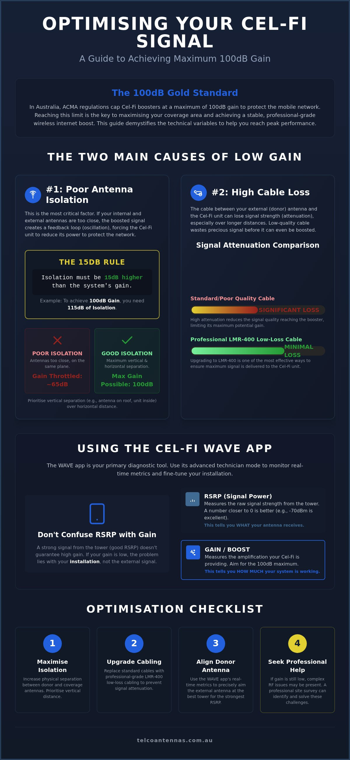
It's common to confuse RSRP (Reference Signal Received Power) with gain. RSRP measures the raw power of the signal coming from the tower, typically expressed as a negative number like -90dBm. A strong RSRP doesn't guarantee high gain. You could have a perfect -70dBm signal at the donor antenna, but if your internal and external antennas lack sufficient physical separation, the system might only provide 60dB of gain instead of 100dB. To improve cel-fi signal gain, you must look at the "Boost" or "Gain" figure in the WAVE app rather than just the signal bars. If the RSRP is excellent but the gain is low, the bottleneck is almost certainly antenna isolation or cable loss rather than tower proximity.
The Physics of Isolation: The #1 Factor in Improving Gain
Isolation refers to the physical and electronic separation between the donor antenna, which communicates with the mobile tower, and the coverage antenna, which rebroadcasts the signal inside your building. If these two antennas are too close, the boosted signal from the internal antenna leaks back into the external antenna. This creates a feedback loop known as oscillation, much like a microphone placed too close to a speaker. To improve cel-fi signal gain, you must first solve this isolation challenge. Cel-Fi units are engineered with sophisticated echo-cancellation, but they will always prioritise network safety by throttling gain if they detect a feedback loop. This protective measure is a core requirement of technical standards, such as the FCC signal booster regulations and similar ACMA rules in Australia, which prevent consumer devices from disrupting the wider mobile network.
The most important technical metric to remember is the 15dB rule. A Cel-Fi system requires the isolation between antennas to be at least 15dB higher than the gain it is attempting to provide. If you want to achieve the maximum 100dB gain, your installation must provide at least 115dB of isolation. If your environment only provides 80dB of isolation, the booster will automatically cap itself at 65dB of gain, regardless of how strong the external signal is. This is why the "search for signal" phase during the initial boot-up is so critical; the unit is measuring this isolation to determine its safe operating ceiling.
Vertical vs. Horizontal Separation
Distance alone is often insufficient to achieve high isolation. Vertical separation is far more effective than horizontal distance because of the radiation patterns of most antennas. Most donor antennas have a "null" or a blind spot directly below them. By stacking antennas vertically, placing the donor antenna on a high mast and the internal antenna on a lower floor, you take advantage of this null to significantly increase isolation. For multi-storey Australian dwellings, this vertical offset is often the only way to hit 100dB gain without moving the antennas hundreds of metres apart.
Using Shielding to Force Higher Gain
Physical barriers act as natural RF shields. In many remote Australian installations, a Colorbond metal roof is your greatest asset. It acts as a massive "baffle" that blocks the internal signal from reaching the external donor antenna. Foil-backed insulation and thick masonry walls provide similar benefits. However, you must be mindful of signal leakage through windows, glass doors, or non-insulated roof cavities. Even a small gap in your shielding can allow enough signal to escape and trigger the Cel-Fi's gain-reduction protocols. If you find your gain is lower than expected, the technicians at Telco Antennas can provide the specialised hardware or advice needed to identify and seal these RF leakage points.
Hardware Optimisation: Cables and Antennas for Maximum Gain
The booster unit is only one component of a high-performing system. Even the most advanced Cel-Fi G41 or ROAM unit cannot compensate for a poor-quality signal delivered via substandard hardware. To improve cel-fi signal gain, you must focus on the physical path the signal travels before it even reaches the booster. This involves understanding signal attenuation, which is the loss of signal strength as it passes through cables and connectors. If your cabling is "eating" 10dB of your signal, you've effectively neutralised a massive portion of your booster's work before the process has started.
In remote Australian environments, the choice of donor antenna is paramount. While omnidirectional antennas are convenient for mobile applications, they lack the focus required for weak-signal areas. High-gain directional antennas, such as Yagis or LPDAs, are engineered to concentrate their "vision" on a single carrier tower. This focus doesn't just increase raw power; it significantly improves the Signal-to-Interference-plus-Noise Ratio (SINR). A cleaner signal with less background noise allows the Cel-Fi's internal processor to maintain a more stable 100dB gain without constantly adjusting for interference. These technical safety standards are globally recognised, mirroring the rigorous FCC rules for signal boosters that ensure these devices enhance connectivity without polluting the wider cellular network.
The LMR-400 Advantage
Standard coaxial cables like RG-58 are frequently bundled with entry-level kits, but they're unsuitable for professional-grade installations. At common 4G and 5G frequencies, RG-58 can lose nearly 0.6dB per metre. In contrast, professional-grade LMR-400 cabling reduces this loss to approximately 0.2dB per metre. Over a typical 15-metre run from a roof-mounted antenna to a booster, switching to LMR-400 can save over 6dB of signal. This might seem like a small number, but because the dB scale is logarithmic, a 6dB saving represents a fourfold increase in signal power reaching your booster. Always ensure your N-type connectors are weatherproofed with self-amalgamating tape to prevent moisture ingress, which can cause rapid corrosion and massive signal loss.
MIMO Antennas and Data Throughput
If your primary goal is a wireless internet boost for high-speed data, a Multiple Input Multiple Output (MIMO) antenna configuration is essential. MIMO uses two separate antenna elements to send and receive data simultaneously over two different paths. For this to be effective, the antennas must be cross-polarised, typically mounted at 45-degree and 135-degree angles. This physical offset ensures the two signals remain distinct, allowing the Cel-Fi to double the potential data throughput. Whether you're mounting on a bull bar bracket for a vehicle or a telescopic mast trailer for a remote site, the stability of the mount is critical. Any movement or vibration in the antenna can cause the Cel-Fi to fluctuate its gain as it attempts to track a moving signal source.
Step-by-Step Guide to Tuning Your Cel-Fi with the WAVE App
The Cel-Fi WAVE app, specifically version 2.1.19 as of August 2026, serves as the essential interface for any professional optimisation. After downloading the app to your mobile device, sync it with your G41 or ROAM unit via Bluetooth. The standard dashboard provides a simplified overview, but to truly improve cel-fi signal gain, you must navigate to the settings menu and enable the "Advanced" or "Technician" view. This reveals the raw decibel figures that dictate your system's performance ceiling and allows you to see exactly where the booster is throttling power.
One of the most underutilised tools in the app is the "Antenna Position Test." This feature allows you to sample the signal at different points without waiting for the booster to fully cycle through its boot sequence. As you adjust your donor antenna, the app tracks the Signal-to-Interference-plus-Noise Ratio (SINR). While monitoring this, you should also observe the "Boost" indicator while testing different coverage antenna locations to ensure the internal signal reaches your desired black spots. A SINR value above 5dB ensures basic connection stability, but you should aim for figures exceeding 15dB to achieve professional-grade data throughput and low latency.
Fine-tuning the Donor Antenna
Optimising a high-gain Yagi antenna requires patience and precision. We recommend rotating the antenna in 5-degree increments, pausing for at least 30 seconds at each position to allow the WAVE app to update the metrics. In fringe areas, you may encounter "tower hopping," where the booster fluctuates between two distant base stations. To resolve this, prioritise a position with a stable, higher SINR over one with a slightly stronger RSRP. A cleaner signal always outperforms a louder, noisier one when it comes to sustained data speeds. This methodical approach ensures you're locked onto the most reliable tower rather than just the closest one.
Troubleshooting Common Error Codes
If your hardware configuration lacks the isolation discussed in previous sections, the WAVE app will likely trigger an E1 or E8 error code, indicating the antennas are "Too Close." This is the system's way of protecting the network from oscillation. When you see these alerts, you must increase the physical distance or add shielding between your antennas. After making any physical adjustments to your cabling or antenna placement, always perform a full power cycle or use the app's "Reset" function to force the unit to recalibrate its gain settings based on the new environment. This ensures the improve cel-fi signal gain protocols are working with the most current environmental data.
The app allows you to lock the unit to your chosen mobile network operator, preventing it from searching for unauthorised networks. If these software adjustments don't resolve your coverage gaps, the engineering team at Telco Antennas can help you interpret your WAVE app logs to identify the specific hardware bottleneck in your installation.
Professional Solutions: When DIY Gain Optimisation Isn’t Enough
Even with the best LMR-400 cabling and a high-gain Yagi, certain geographic and structural challenges remain insurmountable for a standard DIY installation. In deep valleys or heavily timbered terrain, the available donor signal may be so degraded that consumer-grade tools cannot isolate a usable path. To improve cel-fi signal gain in these extreme environments, a shift from basic hardware installation to professional radio frequency (RF) engineering is required. This transition ensures that the physical limitations of the site are bypassed through precise data collection rather than trial and error.
Telco Antennas has provided these specialised engineering services since 2008, bridging the gap between high-performance hardware and the unique challenges of the Australian landscape. Our team focuses on the mechanical and electronic variables that dictate real-world performance. This ensures your Cel-Fi system delivers the stable, high-speed wireless internet boost required for modern operations. Relying on professional expertise ensures that your investment in hardware translates into a reliable communication link that functions correctly in even the most hostile RF environments.
RF Site Surveys and Engineering
A professional RF site survey goes beyond the capabilities of the WAVE app by utilising calibrated spectrum analysers to map the entire local RF landscape. This process identifies the cleanest donor signal, which is often not the strongest one, to ensure the Cel-Fi unit isn't overwhelmed by interference from adjacent towers. For large-scale industrial or agricultural operations, engineers use predictive modelling software to simulate coverage across hundreds of hectares before a single bracket is mounted. This allows for the design of complex multi-antenna systems using custom splitters and balanced cabling runs that maintain the 100dB gain limit across multiple buildings or work zones.
Rapid Deployment with Mast Trailers
Height is frequently the deciding factor in remote connectivity. If local topography or dense vegetation blocks the line-of-sight to the nearest base station, telescopic mast trailers or skids provide a mechanical solution to clear these obstacles. By elevating the donor antenna 10 to 15 metres above the ground, you can often find a significantly cleaner signal that was previously blocked by the treeline. These mobile units are ideal for emergency response or temporary worksites where a permanent communication tower design isn't feasible. If you've exhausted the standard tuning methods and still face connectivity gaps, it's time to enquire about a professional RF site survey today to secure a definitive engineering solution.
Securing Your Professional Signal Foundation
Achieving a reliable connection in remote Australia requires a shift from guesswork to engineering precision. As discussed, the path to improve cel-fi signal gain depends on maintaining strict antenna isolation and eliminating cable loss with high-performance LMR-400. By balancing your RSRP strength with high SINR quality through the WAVE app, you ensure your system operates at its legal 100dB limit rather than being throttled by internal interference. These technical adjustments form the difference between a fluctuating signal and a seamless wireless internet boost.
If your current installation isn't meeting the demands of 2026, our team is ready to assist. We are stockists of genuine LMR-400 and high-gain MIMO antennas, providing Australia-wide shipping and support to even the most isolated sites. You can access technical advice from seasoned RF engineers who understand the mechanics of the Australian landscape. Optimise your signal with professional-grade hardware at Telco Antennas today. With the right hardware and a methodical approach to isolation, stable 5G and 4G coverage is well within your reach.
Frequently Asked Questions
What is a good gain figure for a Cel-Fi GO?
A gain figure of 100dB is the optimal target for any Cel-Fi installation in Australia. This represents the maximum legal limit permitted by the ACMA to ensure network safety. While a connection will function with lower figures, any reading below 70dB usually indicates that the system is throttling its output due to insufficient antenna isolation or a poor donor signal quality.
Why does my Cel-Fi gain drop when I move the antenna?
The gain drops because the unit's internal echo-cancellation algorithm detects a change in the RF environment. If you move the internal coverage antenna closer to the external donor antenna, the system automatically reduces gain to prevent a feedback loop. This protective measure ensures the booster doesn't oscillate and cause interference for other users on the carrier's mobile network.
Can I use any coaxial cable to improve my signal gain?
No, using thin, high-loss cables like RG-58 will actively hinder your efforts to improve cel-fi signal gain. Standard cables attenuate the signal significantly over even short distances, effectively "eating" the gain before it reaches the booster. To maintain maximum signal integrity, you should always utilise professional-grade LMR-400 low-loss cabling with high-quality, weatherproof N-type connectors.
How much distance should be between Cel-Fi antennas?
There is no fixed distance requirement, but you must achieve at least 15dB more isolation than the gain you intend to provide. While 10 to 15 metres of horizontal separation is a common starting point, vertical separation is far more effective. Stacking the donor antenna high on a mast and the coverage antenna inside a lower floor takes advantage of the antenna's radiation patterns to maximise isolation.
Does a higher gain antenna always mean better internet speeds?
Not necessarily, because data throughput is dictated by signal quality (SINR) rather than just raw power. A high-gain antenna is excellent for capturing a signal in fringe areas, but if that signal is congested or noisy, your data speeds will remain low. For a reliable wireless internet boost, you must prioritise a stable SINR figure over simply chasing the highest RSRP strength.
Why is my Cel-Fi showing a "Too Close" error?
The "Too Close" error, often displayed as E1 or E8, indicates that the unit has detected a feedback loop between your antennas. This happens when the boosted signal from the internal antenna is leaking back into the donor antenna. You must increase the physical separation or introduce a substantial RF shield, such as a metal roof or masonry wall, to resolve this oscillation.
Can I boost 5G signal gain with a Cel-Fi GO?
Yes, modern hardware like the Cel-Fi GO G41 is engineered to improve cel-fi signal gain across 5G, 4G, and LTE frequencies. While older, discontinued models like the Cel-Fi PRO were limited to earlier network generations, the 2026 range supports the latest Australian carrier bands. It's essential to ensure your external donor antenna is also rated for the specific 5G frequencies used in your area.
How do I find the nearest Telstra tower to aim my antenna?
You can locate your nearest base station by using the RFNSA database or the ACMA RadComms website. These tools provide the exact coordinates and carrier information for every registered tower in Australia. Once you've identified the tower location, use the "Antenna Position Test" in the WAVE app to fine-tune your Yagi antenna's heading for the best possible signal-to-noise ratio.


