

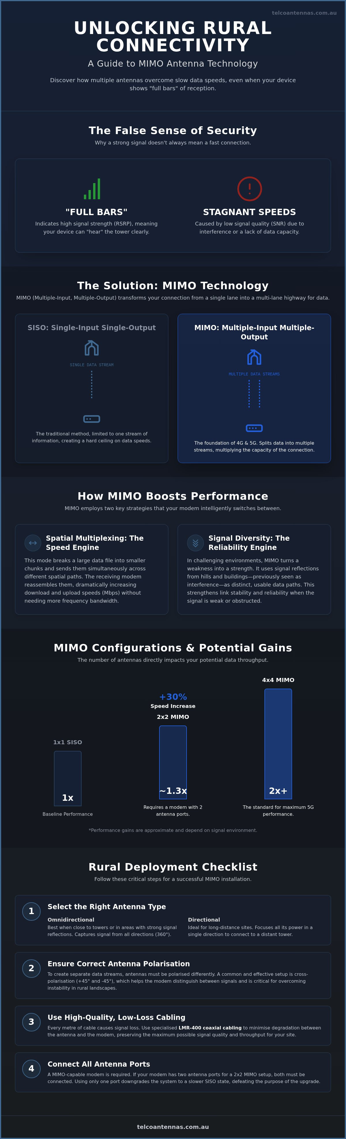
Having "full bars" of reception on a remote site often provides a false sense of security when your actual upload speeds remain frustratingly stagnant. High signal strength does not equate to high data throughput if the underlying radio frequency environment is plagued by interference or inefficient hardware configurations. To overcome these bottlenecks, modern telecommunications rely on mimo antennas to create multiple data paths, effectively multiplying the capacity of a single frequency channel without requiring additional power.
You likely find it confusing when your modem requires two separate antenna leads or your connection drops despite a seemingly strong signal. We recognise that achieving stable connectivity in the Australian outback requires more than just high-gain hardware; it requires a precise understanding of how waves propagate. This guide will help you master the technical principles of spatial multiplexing and antenna polarisation to significantly improve mobile data speeds and link reliability. We will examine the mechanical differences between 2x2 and 4x4 configurations, the impact of specialised LMR-400 cabling, and the specific installation steps required to achieve the maximum theoretical throughput for your site.
Key Takeaways
- Learn how spatial multiplexing enables your hardware to process multiple data streams simultaneously, effectively bypassing the bandwidth limitations of traditional single-antenna systems.
- Understand the technical requirements for 2x2 and 4x4 mimo antennas to ensure your installation is compatible with the latest 5G NR network standards.
- Master the role of antenna polarisation in overcoming signal instability, a common but often overlooked issue in challenging rural Australian landscapes.
- Identify the specific modem connectors and low-loss LMR-400 coaxial cabling needed to achieve the maximum theoretical throughput for your site.
- Gain a clear framework for selecting between omnidirectional and directional hardware based on your proximity to the nearest base station and local terrain.
Understanding MIMO Technology: Why Multiple Antennas Matter
MIMO is a radio communication architecture that utilises multiple antennas at both the source and destination to improve system performance. This approach allows a network to transmit more data simultaneously over the same frequency band by creating multiple spatial paths. Historically, wireless systems relied on SISO (Single-Input Single-Output), where a single transmitter spoke to a single receiver. This older method created a hard ceiling on data speeds because the link was limited to a single stream of information. Modern MIMO (Multiple-Input, Multiple-Output) technology removes this bottleneck by splitting data into multiple streams that travel across separate physical paths.
It serves as the mechanical foundation for both 4G LTE and 5G NR standards. Without it, the high-speed downloads we expect would be mathematically impossible on current spectrum allocations. However, for the system to function, both the base station tower and the user equipment modem must support the same configuration. If your modem has two ports, it's designed for a 2x2 MIMO setup. Connecting only one lead effectively downgrades the device to a SISO state. Research indicates that upgrading from a single antenna to 2x2 mimo antennas can increase connection speeds by approximately 30%, assuming the signal environment is favourable.
The Problem of Multipath Interference
In a perfect world, a radio signal travels in a straight line from the tower to your site. In reality, signals strike buildings, hills, and even trees, causing them to "bounce" and arrive at the receiver at slightly different times. Traditional systems viewed these reflections as destructive interference or noise, which degraded the link. MIMO technology handles this differently. It uses sophisticated digital signal processing to treat these reflections as distinct paths. By installing high-quality mimo antennas, your modem can isolate these "bounced" signals and reassemble them into a single, high-speed data stream, turning a former technical weakness into a performance advantage.
Capacity vs. Coverage: Managing Expectations
A common point of confusion for users on remote sites is the difference between signal strength and data capacity. You might see four bars of reception on your device, which indicates a high Reference Signal Received Power (RSRP), but still suffer from slow speeds. This often happens when the Signal-to-Noise Ratio (SNR) is poor or the link lacks the necessary spatial diversity. While a standard antenna focuses on extending the reach of a signal, MIMO focuses on increasing the volume of data that can pass through that signal. You won't necessarily see more bars on your modem after upgrading, but you will likely observe a significant increase in Mbps. The goal isn't just to "hear" the tower, but to process more information per second.
The Mechanics of MIMO: Spatial Multiplexing and Signal Diversity
The operational effectiveness of mimo antennas rests on two distinct modes of operation: spatial multiplexing and diversity coding. Your modem's chipset acts as the primary controller in this process, constantly evaluating the Signal-to-Interference-plus-Noise Ratio (SINR) to determine the optimal number of data streams. If the environment provides high-quality, distinct signal paths, the system prioritises raw speed. Conversely, if the signal is weak or heavily obstructed, the hardware shifts its focus toward maintaining link stability. This intelligent switching happens thousands of times per second, ensuring that the modem always utilises the most efficient path available.
Spatial Multiplexing: The Speed Engine
Think of spatial multiplexing as a multi-lane highway. In a traditional single-antenna system, all data must travel in a single-file line. By adding additional transmission lanes, spatial multiplexing allows the base station to break a large data file into smaller chunks and send them across different spatial paths at the exact same time. The receiver then uses complex matrix mathematics to distinguish these overlapping signals and reassemble them into the original file. This process is essentially how MIMO increases speed without requiring additional frequency bandwidth. To function correctly, the system requires clear spatial separation between the antennas to ensure the modem can distinguish one stream from another. Spatial multiplexing is the simultaneous transmission of independent data signals through separate spatial channels.
Diversity Coding: The Reliability Engine
There are many instances, particularly in remote Australian environments, where the signal is too degraded to support multiple independent streams. In these scenarios, the system employs diversity coding. Instead of sending different bits of data, the transmitter sends the exact same data bits over multiple paths. If one path is momentarily blocked by terrain or suffers from a sudden fade, the modem can still recover the information from the secondary path. This redundancy is critical for low-latency applications like VoIP calls, video conferencing, or remote telemetry systems where even minor packet loss can cause a total connection failure. For those managing mission-critical infrastructure, conducting a professional RF site survey ensures that the physical environment is capable of supporting the desired MIMO mode. By prioritising reliability over raw throughput when necessary, diversity coding ensures your connection remains active even when environmental conditions are less than ideal.
Comparing MIMO Antenna Configurations: 2x2, 4x4, and Beyond
Selecting the appropriate configuration for your site depends entirely on the capabilities of your modem and the specific frequency bands deployed by your carrier. While earlier 4G LTE deployments relied primarily on two streams of data, the transition to 5G NR has made 4x4 configurations the new baseline for high-capacity networking. It is essential to match the antenna count of your external hardware to the physical ports on your router; using a 2x2 antenna with a 4x4 modem will technically function, but it leaves half of the modem's potential throughput unused.
2X2 MIMO: The Industrial Workhorse
The 2x2 configuration remains the standard for Machine-to-Machine (M2M) applications, IoT sensors, and standard remote office connectivity where gigabit speeds aren't the primary requirement. This setup utilises two separate antenna elements to create two spatial streams. For these mimo antennas to function effectively, the elements must be physically spaced apart or, more commonly, cross-polarised at 45-degree angles. This polarisation ensures that the two signals are mathematically "orthogonal," allowing the modem to distinguish between them even when they occupy the same frequency. You will typically find this hardware in the form of a single panel with two leads or two individual Yagi or LPDA antennas mounted on a single bracket.
4X4 MIMO: Maximising 5G Performance
As Telstra and Optus continue their 5G rollouts, particularly in the 3.5GHz (n78) band, 4x4 MIMO has become necessary to achieve gigabit-class speeds. A 4x4 system doubles the potential throughput of a 2x2 system by utilising four independent data streams. However, this increase in performance comes with a significant increase in installation complexity. A 4x4 setup requires four separate runs of high-quality coaxial cable, such as LMR-400, to connect the antenna array to the modem. Managing these four leads requires careful labelling and cable management to prevent cross-talk and signal attenuation.
When deploying 4x4 mimo antennas, you must choose between an integrated 4-port panel antenna or four discrete directional elements. Integrated panels offer a smaller physical footprint and easier mounting, making them ideal for urban or suburban environments. In contrast, using four discrete directional antennas allows for greater physical separation between elements, which can be advantageous in fringe areas where the modem needs maximum spatial diversity to isolate weak signals from the noise floor. Regardless of the hardware format, ensure your modem chipset is rated for 4x4 operation before investing in the additional cabling and mounting infrastructure required for this configuration.
Critical Factors for Deploying MIMO Antennas in Rural Australia
Deploying mimo antennas in regional Australia presents a unique set of challenges that differ significantly from urban installations. The primary obstacle is the extreme distance between the subscriber site and the nearest Telstra or Optus base station. When a signal travels over vast distances, it is susceptible to atmospheric fading and terrain obstructions that can collapse the multiple spatial streams required for MIMO to function. To maintain these streams, the installation must account for the Fresnel zone, an elliptical area around the line-of-sight path. If terrain or vegetation encroaches upon this zone, the modem may fail back to a single-stream SISO mode, regardless of how many antennas are mounted on the roof.
Mechanical stability is another critical factor often overlooked by DIY installers. High-speed data standards are sensitive to phase shifts in the radio wave. If an antenna mount is flimsy, wind-induced "jitter" can cause rapid fluctuations in signal phase, forcing the modem to constantly renegotiate the link parameters. This results in unstable "bars" of reception and inconsistent throughput. For industrial sites, utilise heavy-duty mounting hardware such as aluminium tri-pods or telescopic masts to ensure the antenna remains perfectly stationary during operation.
Cross-Polarisation: The +/- 45 Degree Rule
Antenna polarisation is perhaps the most significant technical detail for achieving high-speed rural links. For a modem to distinguish between two data streams, the signals must be decorrelated. If you mount two antennas with the same vertical orientation, they will "hear" each other’s signals, causing interference that prevents spatial multiplexing. Mounting two antennas at 90 degrees to each other creates the necessary isolation. In the Australian mobile network, carriers typically use "slant" polarisation. To match this, you should orient your LPDA or Yagi antennas at a 45-degree angle from the vertical, with one tilted to the left (+45°) and the other to the right (-45°). This configuration ensures maximum decorrelation and allows the receiver to isolate each stream with surgical precision.
Cable Selection: Why LMR-400 is Non-Negotiable
The gains achieved by high-performance mimo antennas can be completely negated by poor cable selection. Signal attenuation, or the loss of signal strength as it travels through a wire, is a major bottleneck in rural setups where long cable runs are common. While standard RG-58 cable is thin and easy to route, its high loss profile makes it unsuitable for runs exceeding 5 metres. In contrast, LMR-400 (or LCU400) coaxial cable features a much larger centre conductor and superior shielding, which significantly reduces attenuation. Signal loss in coaxial cables increases with frequency, making low-loss LMR-400 essential for 5G MIMO. If your installation requires a 10-metre run to reach a roof-mounted array, the difference in throughput between RG-58 and LMR-400 can be as high as 50 percent. To ensure your hardware performs to its theoretical limits, you can purchase specialised LMR-400 coaxial cables designed specifically for the Australian climate.
Selecting the Right MIMO Hardware for Your RF Environment
Selecting the correct mimo antennas for your specific location requires a systematic evaluation of your local radio frequency environment. You must balance the need for raw gain against the practicalities of installation and the physical limitations of your user equipment. A mismatch between your hardware and the local signal conditions will lead to suboptimal performance, regardless of the theoretical specifications of your modem. The goal is to create a balanced link budget that provides enough signal margin to maintain multiple data streams without introducing excessive noise.
Directional vs. Omnidirectional MIMO
Directional antennas, such as Log Periodic Dipole Arrays (LPDA), are the preferred solution for fixed installations in rural areas. These units concentrate their energy in a specific direction, which provides high gain but results in a narrow beamwidth. This requires precise alignment with the carrier tower. In contrast, omnidirectional mimo antennas are better suited for mobile applications, such as caravans, or urban sites where the modem can receive signals from multiple towers simultaneously. While they offer lower gain, their 360-degree reception pattern eliminates the need for constant re-alignment. Choosing between them involves a trade-off: directional hardware offers maximum range, while omnidirectional hardware offers versatility in changing environments.
Physical compatibility is the final, often overlooked, hurdle in the selection process. You must confirm whether your modem utilises SMA, N-Type, or TS-9 connectors before finalising your cable assemblies. Industrial routers typically feature robust SMA female connections, whereas consumer-grade mobile hotspots often rely on smaller TS-9 ports that require delicate handling. If you're deploying a 4x4 system, you'll need to manage four separate leads. Ensuring your cable terminations match your modem ports directly prevents the need for adapters, which can introduce unnecessary signal loss and physical points of failure.
The Telco Antennas Engineering Advantage
Achieving maximum throughput requires more than just high-quality hardware; it requires an integrated system design. Small errors in cable termination or antenna placement can lead to significant data loss. Our professional RF site survey and communication tower design services remove this uncertainty by providing a data-driven blueprint for your installation. We ensure that every component, from the low-loss LMR-400 cabling to the aluminium tri-pods, is perfectly matched to your modem's chipset and local network conditions. This consultative approach ensures your equipment functions correctly from the day of installation. If you're managing complex industrial connectivity, consult our RF engineers for a tailored MIMO solution that guarantees reliability in the field.
Achieving Maximum Throughput in the Field
Establishing a reliable, high-speed data link in remote Australia requires a shift from viewing hardware as simple signal collectors to understanding it as part of a complex spatial system. As explored in this guide, the transition from SISO to modern multi-stream architectures is the primary driver of 5G performance. Success on-site depends on the precise execution of technical details, particularly the +/- 45-degree cross-polarisation rule and the use of low-loss LMR-400 cabling to prevent signal attenuation over long runs.
By correctly identifying your modem's capabilities and the local RF landscape, you can move beyond stagnant upload speeds and achieve the maximum theoretical throughput for your equipment. Our hardware is Australian-designed for harsh environments and backed by engineering-led technical support to ensure your installation meets industrial standards. You can optimise your data throughput with Telco Antennas’ range of MIMO hardware, utilising our specialised LMR-400 cabling for zero-compromise performance. With the correct configuration of mimo antennas, consistent and stable connectivity is achievable even in the most challenging geographical locations.
Frequently Asked Questions
Do I need two separate antennas for MIMO to work?
You must have at least two antenna elements to establish a MIMO link. This can be achieved by using two individual antennas, such as LPDAs, or a single panel antenna that contains two separate elements within one enclosure. If your modem has two external ports, it's designed to receive two distinct data streams. Connecting only one antenna forces the device into a single-stream mode, which significantly reduces your potential throughput.
Can I use a single cable with a splitter for a MIMO antenna?
No, you cannot use a splitter to combine MIMO signals into a single cable. Each antenna element requires a dedicated, independent path to the modem to maintain spatial separation. Using a splitter merges these distinct streams into one, which prevents the modem from decoding the data correctly. For optimal results, use separate runs of high-quality LMR-400 cabling for each antenna port on your device.
Does MIMO increase the range of my mobile signal?
MIMO is primarily designed to increase data throughput and link stability rather than raw distance. While the diversity coding used in mimo antennas can make a weak signal more reliable by reducing packet loss, it doesn't extend the physical reach of the tower. If your goal is to connect to a tower over a vast distance, you should prioritise high-gain directional antennas and low-loss cabling.
What is the difference between 2x2 and 4x4 MIMO?
The primary difference lies in the number of simultaneous data streams the hardware can handle. A 2x2 system utilises two antennas to send and receive data, while a 4x4 system uses four. In the Australian 5G landscape, 4x4 is becoming the standard for high-capacity sites. Moving from a 2x2 to a 4x4 configuration can provide a speed increase of up to 70 percent over a single-antenna system.
Why do MIMO antennas need to be cross-polarised?
Cross-polarisation is necessary to prevent the two antenna elements from interfering with each other. By orienting the antennas at 90 degrees to one another, typically at +/- 45-degree angles, the signals become "orthogonal." This allows the modem to isolate and process each stream independently. Without this physical separation of the signal's wave orientation, the modem would struggle to distinguish between the overlapping data paths.
Will a MIMO antenna work with my existing 4G or 5G modem?
Most modern 4G and 5G industrial modems are compatible with mimo antennas, provided they have multiple external antenna ports. You should check the back of your device for SMA or TS-9 connectors. If your modem only has a single port, it's a SISO (Single Input Single Output) device and cannot utilise MIMO technology. Always verify your modem's specifications to see if it supports 2x2 or 4x4 configurations.
How far apart should I mount two separate MIMO antennas?
If you're using two separate directional antennas, aim for a minimum physical separation of 600mm. For lower frequency bands used in rural Australia, increasing this distance to one metre can improve spatial diversity. This separation helps the modem distinguish between the signals more effectively. If you're limited by mounting space, ensure you at least utilise cross-polarisation to maintain signal decorrelation.
Is it better to have one 4x4 antenna or four individual antennas?
A single 4x4 panel antenna is often the most pragmatic choice for residential or light commercial installations due to its simplified mounting and smaller footprint. However, four individual directional antennas can be superior for fringe locations. This setup allows for maximum physical separation and the ability to fine-tune the alignment of each element. This level of control is often necessary to isolate weak signals in high-noise environments.
More Articles

Cambium cnWave 60 GHz vs licensed microwave link: a 2026 cost comparison

GME Antenna Spring Base vs RFI Heavy Duty Spring Base: Which Is More Durable?
