
The highest dBi rating on a retail box often results in the poorest real-world performance when you're at the edge of a cell tower's reach. While cheap plastic antennas promise massive gains, they frequently fail to deliver the signal quality required to maintain a stable 4G or 5G connection. You've likely experienced the frustration of data speeds cratering during peak times or video calls dropping out exactly when you need them for work or safety. It's an exhausting cycle of troubleshooting equipment that simply isn't fit for purpose.
This guide will help you master the technical requirements for a professional-grade MIMO antenna for fringe areas to ensure stable high-speed data in regional black spots. We'll explain why a low-loss system architecture, featuring LMR-400 cabling and 4x4 MIMO arrays, has become the baseline for 5.5G performance in 2026. You'll learn how to identify genuine hardware that withstands harsh Australian environmental conditions and provides the reliability your remote operations demand. We'll move from basic signal theory to the mechanical solutions that turn a weak, fluctuating connection into a dependable business-grade link.
Key Takeaways
- Understand the mechanics of how MIMO technology utilises signal multipath to sustain data throughput in locations where carrier signals are significantly attenuated.
- Learn why a high-gain directional MIMO antenna for fringe areas is the engineering standard for overcoming path loss and extreme distance from the nearest cell tower.
- Discover why LMR-400 low-loss coaxial cabling is a non-negotiable component for preserving signal quality and preventing the attenuation that occurs with standard RG58 cables.
- Master the technical deployment steps, including the use of ±45° cross-polarisation (X-Pol) and precise boresighting, to achieve stable connectivity in regional black spots.
- Identify the importance of professional RF site surveys to determine the optimal tower alignment and frequency bands for your specific geographic location.
Understanding the Physics of Fringe Areas and MIMO Mechanics
In the Australian context, a "fringe area" isn't merely a point on a map far from a town centre. It's a complex intersection where geographic distance, local topography, and cell tower capacity collide. As you move further from a base station, the radio frequency (RF) energy disperses, leading to a drop in Reference Signal Received Power (RSRP). However, terrain obstacles like ridges or dense eucalyptus stands further attenuate this signal, while the limited capacity of a distant tower can lead to significant congestion during peak periods. Selecting a high-quality MIMO antenna for fringe areas requires understanding that you aren't just fighting distance; you're fighting the physics of signal degradation and interference.
The core of modern 4G and 5G connectivity is MIMO (Multiple-Input, Multiple-Output) technology. In urban environments, MIMO thrives on "multipath" interference, where signals bounce off buildings to reach your device from multiple angles. In rural fringe areas, these reflections are often non-existent. When the signal is weak and the path is direct but obstructed, the modem struggles to distinguish between the intended data stream and background thermal noise. This is why a standard "one-size-fits-all" retail antenna often fails in the bush; it lacks the precision to isolate the signal from the surrounding noise floor.
The Role of RSRQ and SINR in Data Stability
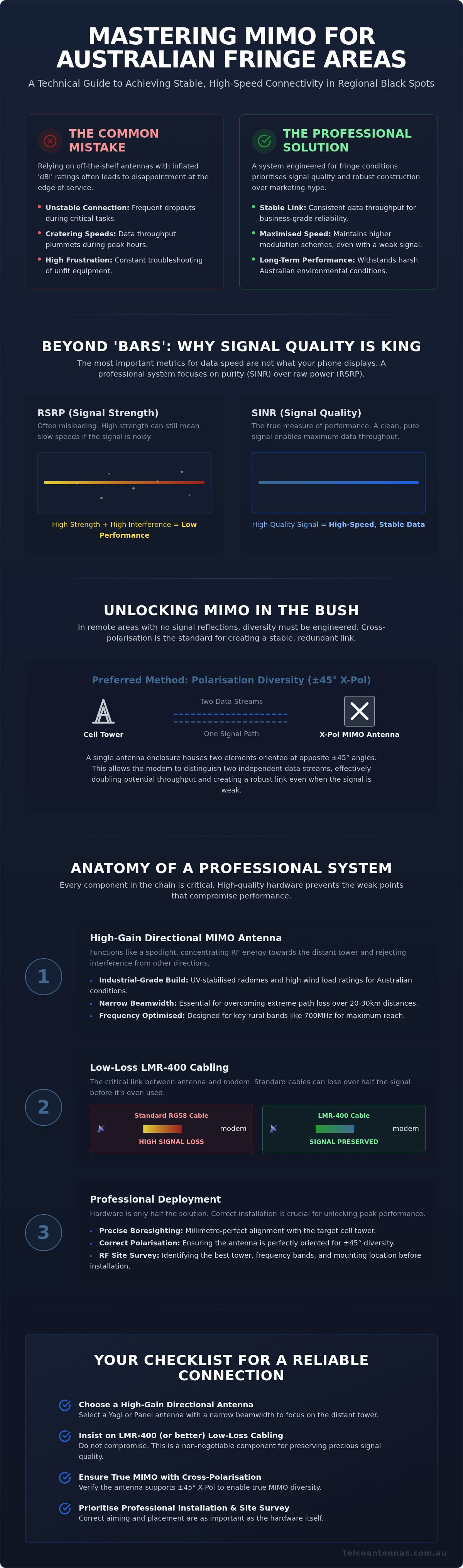
Many users equate "full bars" with high-speed internet, but this is a technical fallacy. Your device's bars usually represent RSRP (strength), but the real driver of throughput is the Signal-to-Interference-plus-Noise Ratio (SINR). If you use a cheap, poorly filtered antenna, you might increase your signal strength while simultaneously amplifying background interference. This results in a high RSRP but a disastrously low SINR. For a MIMO antenna for fringe areas to be effective, it must prioritise signal purity over raw amplification. Without a clean SINR, your modem will constantly downshift its modulation scheme. This leads to the sluggish speeds and high latency that prevent reliable remote work or video streaming.
MIMO Diversity: Spatial vs. Polarisation
MIMO requires at least two distinct paths for data to travel simultaneously to function correctly. In remote settings where natural multipath reflections are scarce, we must "engineer" this diversity. This is achieved through two primary methods:
- Spatial Diversity: Physically separating two antennas, usually by a minimum of 60 to 100 centimetres, so they receive the tower signal from slightly different perspectives.
- Polarisation Diversity: Using a single enclosure with two antenna elements oriented at opposite angles, typically ±45° (dual-slant).
In Australian fringe deployments, dual-slant polarisation is the preferred mechanical solution. It ensures that even when the signal is weak, the modem can maintain two independent data streams. This configuration effectively stabilises the link and provides the necessary redundancy to survive the fluctuating conditions of a regional network.
Selecting the Optimal MIMO Antenna Type for Your Site
Selecting the right hardware is a matter of matching the antenna's physical properties to your site's specific RF profile. While retail marketing often suggests a single antenna can solve every connectivity issue, the reality of the Australian landscape requires a more nuanced approach. A high-performance MIMO antenna for fringe areas must be selected based on its gain, beamwidth, and frequency band compatibility, particularly for the 700MHz spectrum which provides the backbone of rural 4G and 5G coverage. Beyond electrical specs, the physical build must be industrial-grade; any hardware deployed in regional Australia needs UV-stabilised radomes and high wind load ratings to survive intense summer heat and seasonal storms.
Directional MIMO Arrays: The Spotlight Effect
Directional antennas, such as Yagi-Uda arrays or high-gain panels, function like a spotlight. They concentrate all available RF energy into a narrow beam, which is essential when the cell tower is 20 or 30 kilometres away. This narrow beamwidth also provides a secondary benefit: it rejects interference from other towers or noise sources that fall outside the main lobe. For fixed installations, a dual-polarised panel is often the most practical solution, as it houses two antenna elements in one weather-sealed enclosure. However, for extreme fringe sites, using two separate high-gain Yagi antennas mounted at 90-degree angles to each other provides the maximum possible isolation. Achieving success requires precise boresighting, the process of aligning the antenna's centre axis directly with the tower's sector. If you're unsure of your local tower's location, conducting a professional RF site survey can provide the exact coordinates needed for alignment.
Omnidirectional Antennas: When (and When Not) to Use Them
Omnidirectional antennas are designed to receive signals from a 360-degree radius. This makes them ideal for mobile applications, such as caravans, boats, or service vehicles, where the orientation to the tower is constantly changing. In a stationary fringe environment, however, this 360-degree sensitivity becomes a liability. An omnidirectional antenna lacks the gain necessary to reach out to distant towers and will simultaneously pull in background noise from every direction, significantly degrading your SINR. While they're convenient, they're rarely the correct choice for a permanent residence or office in a regional black spot. For these sites, the trade-off of a more complex installation for a directional array is always rewarded with higher data stability and more consistent throughput. The myth of the universal antenna often leads to wasted investment; always prioritise the "spotlight" of a directional system when the tower location is fixed.
Overcoming Distance: Gain, Polarisation, and Path Loss
Achieving a stable connection in the Australian bush requires a clear understanding of how radio frequency energy behaves over vast distances. Gain, measured in dBi, is frequently marketed as a power boost, but it's more accurately described as a concentration of energy. A high-gain MIMO antenna for fringe areas doesn't create more signal; it reshapes the antenna's radiation pattern to focus on a specific point, much like a magnifying glass focuses sunlight. This concentration is vital for counteracting Free Space Path Loss (FSPL), where signal strength naturally dissipates as it travels through the atmosphere. This effect is particularly aggressive on higher 5G frequency bands, such as 3.5GHz, which attenuate far more rapidly than the lower 700MHz bands commonly used for regional coverage.
Topography presents the next significant hurdle. Even with high-gain hardware, physical obstructions like rolling hills or dense vegetation can absorb or reflect signals before they reach your site. Successful fringe deployments must account for the Fresnel zone, an elliptical area around the line-of-sight path that must remain clear of obstructions. If trees or buildings encroach on this zone, the resulting diffraction can lead to signal fading and high packet loss, even if you can technically "see" the tower from your roof.
The Critical Importance of Cross-Polarisation
While many retailers focus solely on dBi, polarisation is often the deciding factor in MIMO efficiency. Modern Australian cell towers transmit data on two distinct planes to maximise throughput. In regional areas, carriers typically utilise "dual-slant" polarisation, where signals are sent at ±45° angles rather than traditional vertical or horizontal orientations. This is known as Cross-Polarisation (X-Pol).
Matching your antenna's orientation to the tower's transmission is mandatory for maintaining a high Receive Signal Level (RSL). If your antenna elements are vertically polarised while the tower is using a ±45° slant, you can experience a cross-polarisation discrimination loss of 20dB or more. This massive drop in signal quality can effectively neutralise the benefits of a high-gain antenna. When installing your array, ensure the internal elements are correctly oriented to the carrier's local configuration to preserve the integrity of both MIMO data streams.
Navigating Line-of-Sight (LoS) Challenges
There's a distinct difference between optical line-of-sight and radio line-of-sight. Just because a tower is visible through binoculars doesn't mean the RF path is clear. To overcome local terrain obstacles and clear the Fresnel zone, elevation is your most effective tool. Using topographic maps and tower locators allows you to calculate the minimum height required to establish a clean link.
In many rural scenarios, mounting an antenna on a standard roof gutter isn't sufficient. If your site is in a valley or behind a significant tree line, you may need to utilise specialised mounting hardware. Solutions like an aluminium tri-pod or a telescopic mast trailer can provide the necessary elevation to clear local obstructions. These structures allow you to position your MIMO antenna for fringe areas above the "noise" of the ground level, significantly reducing path loss and providing the modem with the cleanest possible signal to process.
The Critical Link: Minimising Loss with LMR-400 Cabling
The efficiency of a MIMO antenna for fringe areas is fundamentally limited by the physical quality of the coaxial cable connecting it to the modem. In the industry, we refer to poor cabling as the "Invisible Thief" because it can silently strip away the hard-won gain of a high-performance antenna before the signal ever reaches your device. While standard RG58 or RG6 cables are common in basic retail kits, they are technically unsuitable for long runs in regional settings. As frequency bands increase, specifically when targeting the 2600MHz (Band 7) or 3500MHz (5G) spectrums, the signal's ability to travel through the copper core of a thin cable diminishes rapidly. This results in high-frequency data links being significantly more vulnerable to cable-induced degradation than lower-frequency 700MHz bands.
Connector integrity is equally vital for maintaining a low-noise environment. For outdoor deployments, N-Type connectors are the professional standard due to their rugged, weatherproof design and superior RF shielding. On the modem side, smaller SMA or TS-9 connectors must be precision-engineered to ensure a tight impedance match. Any loose connection or oxidised interface introduces signal leakage and interference, which can cripple the throughput of even the most expensive MIMO array. Ensuring every component in the chain meets these engineering standards is the only way to guarantee a reliable link.
Calculating Your System Link Budget
A professional installation requires a "link budget" calculation to ensure the net gain remains positive. The formula is straightforward: Antenna Gain minus Cable Loss minus Connector Loss equals your Net Gain. If you install a high-gain 15dBi antenna but use a 10-metre run of standard RG58 cable, you could lose up to 10dB of that signal just in the wire, effectively turning a professional array into a basic stubby antenna. Attenuation refers to the reduction in signal strength as it travels through a medium, with professional-grade LMR-400 coaxial cables typically losing only approximately 0.22 dBi per metre at 2500MHz. By switching to LMR-400, you preserve the majority of the antenna's performance, ensuring the modem receives a signal strong enough to maintain stable data speeds.
Best Practices for RF Cabling Installation
Mechanical handling during installation dictates the long-term reliability of your system. Coaxial cables have a minimum bend radius that must be respected; sharp bends or kinks can crush the internal dielectric, leading to impedance mismatches and a high Voltage Standing Wave Ratio (VSWR). This causes signal energy to reflect back toward the antenna rather than flowing to the modem. Additionally, moisture is the primary enemy of RF performance. Every outdoor connection must be sealed with self-amalgamating tape or weatherproofing boots to prevent moisture ingress and subsequent oxidation of the copper conductors. To ensure the highest system integrity, we recommend using pre-terminated, factory-tested LMR-400 assemblies. These are tested for VSWR and insertion loss before shipment, eliminating the variables and potential failure points of manual field crimping.
Professional Deployment: Moving from Hardware to Solution
Deploying a MIMO antenna for fringe areas requires more than just mounting hardware on a roof. It's the final stage of an engineered solution where physical placement and software diagnostics converge. Once you've established your link budget and selected your LMR-400 cabling, the focus shifts to boresighting. This is the methodical process of aligning your directional antenna's centre axis with the specific sector of the cell tower. Because high-gain antennas have narrow beamwidths, even a five-degree misalignment can result in a significant drop in signal quality. Using a compass and GPS coordinates from tower databases, you must lock the antenna into a position that maximises the Signal-to-Interference-plus-Noise Ratio (SINR) rather than just raw signal strength.
In many regional Australian scenarios, users require both high-speed data and reliable voice calls. Integrating your MIMO array with Cel-Fi GO mobile signal boosters allows you to achieve this parity. While the MIMO antenna handles the high-speed data throughput for your modem, the booster ensures that mobile handsets within the building maintain a stable connection to the carrier network. Final testing must be conducted during peak network times. By using your modem's internal diagnostics to monitor SINR and RSRQ (Reference Signal Received Quality), you can confirm that your installation has successfully mitigated the "noise" of the fringe environment and established a stable, long-term link.
Why an RF Site Survey is Essential for Remote Sites
Relying on the signal bars on a smartphone is a common mistake in regional deployments. Phones are programmed to stay connected to the "strongest" tower, which isn't always the one with the best data capacity or the least congestion. A professional RF site survey uses calibrated spectrum analysers to identify "hidden" towers and evaluate band availability across the 700MHz to 3500MHz spectrum. Our engineers use this data to design bespoke systems for industrial fringe areas, ensuring that the hardware is tuned to the specific frequencies and topographical challenges of the site. This removes the guesswork and prevents the costly trial-and-error often associated with DIY installations.
Next Steps: Upgrading Your Fringe Connectivity
Deciding between a standard DIY kit and a professionally designed system depends on the criticality of your connection. For remote businesses or homesteads where safety and operation depend on connectivity, an engineered approach is non-negotiable. This might include integrating a MIMO antenna for fringe areas with a hybrid setup, such as using Starlink aftermarket power conversion to maintain a secondary satellite link alongside your 4G or 5G primary connection. This redundancy ensures that your site remains online even during carrier outages or extreme weather events. To move forward with a system that is guaranteed to perform in your specific location, you should Consult with a Telco Antennas specialist for a custom link design. Our team focuses on the mechanics of the industry to provide tools that function correctly in the most challenging real-world environments.
Establishing Long-Term Regional Connectivity
Achieving stable high-speed data in remote black spots is a matter of precision engineering rather than luck. Success depends on moving beyond basic retail hardware and focusing on a system-wide approach. This involves prioritising high-gain directional arrays, matching tower polarisation, and eliminating the signal loss caused by inferior cabling. By implementing a professional-grade MIMO antenna for fringe areas alongside LMR-400 coaxial cables, you can transform a fluctuating link into a dependable business asset.
As an Australian-owned and operated specialist since 2008, Telco Antennas maintains an extensive inventory of industrial hardware and provides expert RF engineering services for the most challenging remote sites. Our team focuses on the technical nuances that ensure your equipment survives harsh environmental conditions and delivers the performance you expect. Optimise your fringe area connectivity with an engineered MIMO solution from Telco Antennas. With the right architecture in place, you'll finally have the reliable connection you need to work and live safely in the bush.
Frequently Asked Questions
What is the best MIMO antenna for a fringe area with no line-of-sight?
A high-gain directional array is the most effective choice when direct line-of-sight is obstructed by terrain or vegetation. These antennas utilise lower frequency bands, such as the 700MHz spectrum, which possess superior diffraction properties to bend over hills or penetrate foliage. In these scenarios, a MIMO antenna for fringe areas should be mounted as high as possible to clear the immediate Fresnel zone and capture reflected or diffracted signals from the landscape.
Can I use a MIMO antenna with a Cel-Fi GO booster in a regional black spot?
You can use a MIMO antenna with a Cel-Fi GO, but you will typically only utilise one of the antenna's leads, as these boosters are designed for single-antenna donor inputs. If your primary goal is high-speed data, it's better to connect the MIMO antenna directly to a compatible modem. For sites needing both boosted voice and fast data, we often design systems that split the signal or use dedicated antennas for each device.
How much dBi gain do I actually need for a remote 4G/5G connection?
For most remote Australian sites, a gain of 11dBi to 15dBi is the standard requirement for a stable connection. It's a common misconception that more is always better; excessively high gain results in an extremely narrow beamwidth that is difficult to align and maintain. The goal is to provide enough concentration of energy to overcome path loss while maintaining a wide enough lobe to account for slight mast movement in high winds.
Does the length of the coaxial cable affect my internet speed in fringe areas?
Cable length has a direct impact on performance because every metre of copper introduces attenuation. In fringe areas, using thin RG58 cable over a 10-metre run can lose more than half of your signal strength before it reaches the modem. This is why we specify LMR-400 low-loss cabling for any run exceeding three metres. Preserving the signal quality (SINR) is just as important as the raw strength captured by the antenna.
What is the difference between a directional and omnidirectional MIMO antenna?
A directional antenna concentrates signal in one direction like a spotlight, whereas an omnidirectional antenna receives from all 360 degrees like a lantern. Directional models provide the high gain and noise rejection necessary for fixed rural sites. Omnidirectional antennas are better suited for mobile applications like caravans where the tower direction changes constantly. For a stationary regional black spot, a directional MIMO antenna for fringe areas is almost always the superior choice.
Is a 5G MIMO antenna backwards compatible with 4G networks in rural Australia?
Yes, a 5G-rated MIMO antenna is fully backwards compatible with 4G and 3G networks, provided it supports the relevant frequency bands. Most modern industrial antennas cover a wide broadband range from 698MHz to 3800MHz. This ensures they can capture the 700MHz 4G signals used for long-distance rural coverage while remaining ready for 5G deployments as carriers upgrade their regional base stations over the coming years.
How do I align a directional antenna for the best signal quality?
Aligning a directional antenna involves a methodical process called boresighting, where you rotate the array in small increments while monitoring modem diagnostics. You should prioritise the Signal-to-Interference-plus-Noise Ratio (SINR) over the number of signal bars. Because digital signals have a slight processing delay, you must wait approximately 30 seconds after each adjustment to allow the modem to report an accurate RSRQ and RSRP reading from the tower.
Can I mount a MIMO antenna on a Starlink mast or tripod?
You can certainly mount a MIMO antenna on a Starlink mast or an aluminium tri-pod, provided the mounting brackets are compatible with the pole diameter. Many rural users adopt a hybrid approach by co-locating their cellular and satellite hardware on a single telescopic mast to simplify cabling and grounding. Ensure there is sufficient physical separation between the antennas to prevent near-field interference, which can degrade the performance of both systems.


