
What if the Starlink dish isn’t the biggest source of battery drain in your setup? In the starlink 12v conversion kit vs pure sine wave inverter power draw comparison, the inverter’s own consumption and the losses from converting battery DC to AC, then back to DC, can change the result. A dish’s headline wattage won’t show the full load on your battery.
If you’ve seen conflicting power figures, estimating runtime can feel uncertain. Results depend on the Starlink model, its operating conditions and the equipment between the battery and the dish. A figure measured at the appliance may not reflect what the battery supplies.
This article compares both power paths against the same Starlink load, focusing on total battery-side draw rather than isolated device readings. It explains how conversion losses and inverter standby consumption affect the comparison, why model compatibility matters and how to estimate runtime under realistic conditions. Use these factors to decide whether a direct 12V conversion kit or an inverter setup better suits your installation.
Key Takeaways
- Compare the complete power path at the battery, not just the Starlink terminal’s stated consumption.
- The starlink 12v conversion kit vs pure sine wave inverter power draw depends on each setup’s conversion losses and standby consumption, so savings aren’t universal.
- Measure each complete setup under comparable operating conditions with a suitable DC power meter, following the meter manufacturer’s instructions.
- Estimate runtime using measured battery-side consumption and usable battery capacity, allowing for changes in Starlink activity.
- Choose a power path that matches your Starlink model and battery system, and consider whether you also need AC power for other equipment.
Starlink 12V conversion kit vs inverter: why battery-side power draw matters
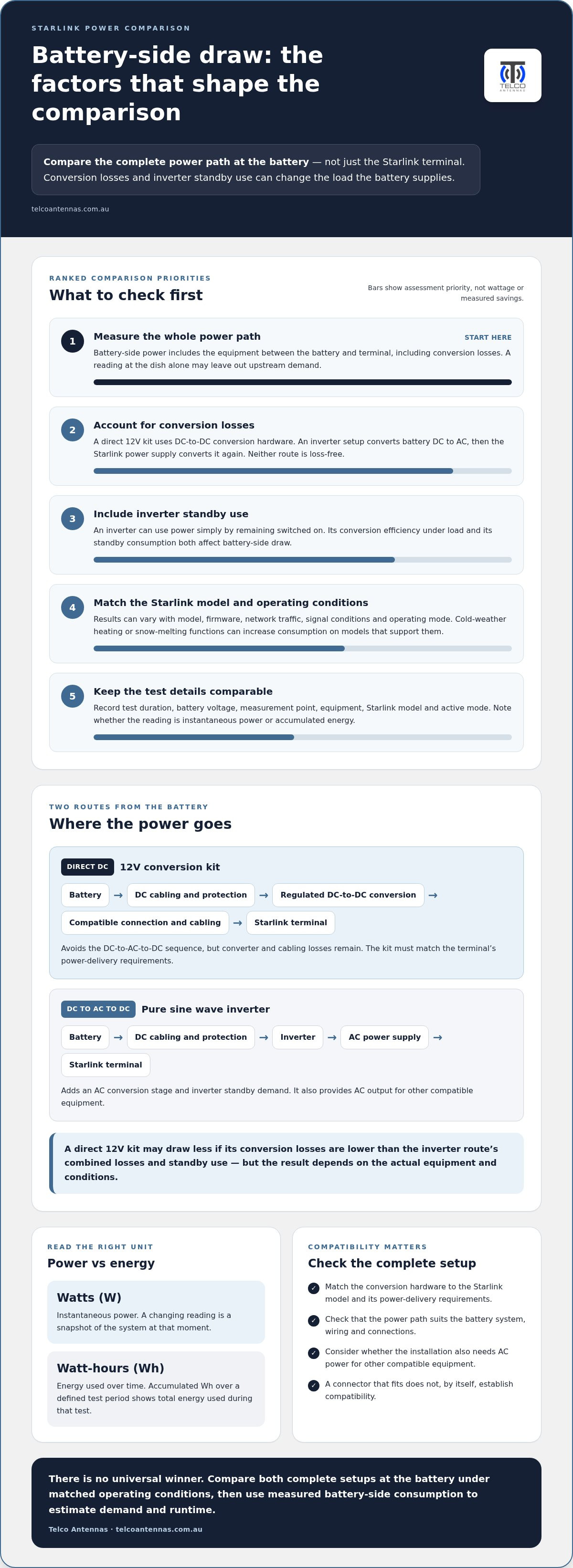
To compare a direct 12V conversion kit with an inverter fairly, measure what the entire power path takes from the battery. The Starlink terminal’s consumption is only part of the load. Conversion hardware and an inverter or power supply also use energy, including while the terminal is operating.
Battery-side power draw is the electrical power drawn from the battery by the entire system required to run Starlink, including losses in the equipment between the battery and the terminal. It’s the useful figure for estimating battery demand and runtime, rather than a reading taken at the dish alone.
What does power draw mean in a Starlink setup?
Watts (W) describe instantaneous power, while watt-hours (Wh) describe energy used over time. A reading that changes as Starlink operates is a snapshot. Watt-hours accumulated over a defined period show how much energy the system used during that test.
In a DC setup, power travels from the battery through conversion hardware to the Starlink equipment. In an inverter setup, the battery supplies a power inverter, which changes DC into AC for the Starlink power supply to convert again. A device’s rated or measured load may exclude upstream conversion losses, so the measurement point matters.
Why can two Starlink power tests report different results?
Results can differ because tests may use different Starlink models, firmware, network traffic, signal conditions or operating modes. Environmental conditions matter too: cold-weather heating or snow-melting functions can increase consumption on models that support them. A brief reading during a higher-demand mode may not represent a longer period of typical operation.
For a meaningful comparison, record the conditions alongside each figure:
- Test duration: state how long the system ran and whether the reading is instantaneous or accumulated energy.
- Battery voltage and measurement point: note the voltage during testing and whether the meter measured at the battery or closer to the Starlink equipment.
- Equipment and operating conditions: identify the meter and power configuration, as well as the Starlink model and active mode.
Without those details, two reported numbers may describe different parts of the power chain or different operating conditions. That’s why the starlink 12v conversion kit vs pure sine wave inverter power draw comparison needs matched tests at the battery before it can inform a practical runtime estimate.
How a 12V conversion kit and pure sine wave inverter power Starlink
Both setups start with the battery, but deliver power to Starlink through different conversion stages. A direct 12V kit uses DC-to-DC conversion hardware matched to the Starlink equipment. An inverter setup first creates AC power, which the Starlink power supply then converts for the terminal. Neither route is loss-free, and the exact components depend on the battery system and Starlink model.
Direct DC route: Battery → DC cabling and protection → regulated DC-to-DC conversion hardware → model-compatible connection and cabling → Starlink terminal.
Inverter route: Battery → DC cabling and protection → pure sine wave inverter → AC cabling → Starlink power supply → model-compatible connection and cabling → Starlink terminal.
What the 12V conversion path changes
A conversion kit adjusts and regulates battery voltage to suit the Starlink equipment, avoiding the DC-to-AC-to-DC sequence. It still uses energy: the converter and cabling have losses, so direct DC isn’t loss-free. Input ranges, wiring and connections depend on the particular kit and Starlink model. The hardware must match the terminal’s power-delivery requirements. A connector that fits does not, by itself, establish compatibility.
What the pure sine wave inverter path adds
A pure sine wave inverter changes battery DC into AC. The Starlink power supply then converts that AC into the DC power the equipment needs. Conversion efficiency describes how much input power is required under load, while no-load or standby consumption is the power the inverter uses simply by remaining switched on. Both affect battery-side draw and explain why the battery may supply more power than the AC load receives.
The inverter’s practical advantage is that it provides AC output for other compatible equipment. That can make sense if your installation already needs AC. If Starlink is the only load, this flexibility may come with an extra conversion stage and standby demand. The balance depends on the inverter, conversion kit, operating load and how long the system runs.
That’s the basis of a fair starlink 12v conversion kit vs pure sine wave inverter power draw comparison: assess the complete chain, not just the terminal. Telco Antennas supplies Starlink aftermarket power conversion for matched setups. Find details about Starlink aftermarket power conversion as you plan your installation.
Which setup draws less power? Compare both at the battery
A 12V conversion kit may draw less from the battery if its conversion losses are lower than the combined losses and standby consumption of the inverter route. It isn’t automatically the winner: results depend on the particular kit, inverter, Starlink equipment and operating conditions. Compare complete setups using measurements taken at the same point.
| Factor | 12V conversion kit | Pure sine wave inverter |
|---|---|---|
| Conversion stages | Battery DC passes through DC-to-DC conversion hardware before reaching Starlink. | Battery DC becomes AC at the inverter, then the Starlink power supply converts it for the terminal. |
| Standby draw | Depends on the conversion hardware and whether it remains energised. | Depends on the inverter’s no-load consumption and whether it stays switched on. |
| Compatibility | Kit must suit the Starlink model and its power-delivery requirements. | Inverter output and the Starlink power supply must be suitable for the equipment. |
| Setup | Requires compatible conversion hardware, wiring and connections. | Retains an AC supply, which can also power other compatible equipment. |
| Measurement point | Measure the complete setup at the battery. | Measure the complete setup at the battery, including inverter consumption. |
Make the comparison like for like
Use the same Starlink model, operating mode, workload and test duration for both configurations. Measure DC voltage and current at the battery with suitable equipment, and record ambient conditions, connected peripherals and intermittent high-load functions. A reading at the Starlink terminal or inverter output won’t capture the entire battery load.
For a changing load, use a meter that records energy over the test period. If calculating from average readings, battery-side power is voltage multiplied by current, and estimated energy is average power multiplied by operating time. Record the test inputs and measurement method. Without verified measurements, a numerical example could imply more precision than the comparison supports.
Put any difference in context
Compare the watt-hours drawn from the battery under matched operating conditions. Then relate that difference to daily operating hours and usable battery capacity. A modest reduction may matter during long off-grid operation, but may not justify extra wiring or equipment if an inverter is already needed for shared AC loads. Include compatibility and installation complexity in the decision, alongside measured consumption.
The starlink 12v conversion kit vs pure sine wave inverter power draw question is best answered by testing the actual power chain you plan to use, rather than relying on a general claim about either approach.
How to measure power draw and estimate Starlink runtime
A repeatable test measures the complete setup at the battery, then uses the observed energy consumption to estimate runtime. Don’t infer battery demand from a Starlink terminal reading alone. Model-specific power requirements and equipment limits vary, so verify them against the documentation for the exact terminal, conversion hardware, inverter and battery.
A repeatable measurement process for both power paths
- Identify the equipment. Record the Starlink model, power configuration, battery type and capacity, and the meter being used. Note any connected peripherals.
- Set consistent test conditions. Use the same Starlink operating mode, network workload and test duration for each setup. Record ambient conditions and any intermittent high-load functions.
- Measure at the battery. Use a suitable DC power meter installed to measure the complete configuration’s battery input. Follow the meter manufacturer’s instructions and the equipment documentation. If you’re unsure how to connect the meter safely, don’t alter the wiring yourself.
- Log the readings. Record battery voltage, current and cumulative watt-hours, along with the measurement location and instrument. Repeat the procedure for the other power path under comparable conditions.
Keep wiring and protection appropriate to the installation, and don’t disconnect or modify live equipment to take a reading. A meter’s cumulative watt-hour reading is useful because it captures changing demand over the test instead of relying on a momentary snapshot.
Turn measured consumption into a useful runtime estimate
If your meter records energy over a test, divide the watt-hours used by the test duration in hours to get average power in watts. Alternatively, estimate energy demand by multiplying average measured watts by operating hours. Use your own measured average and planned run time, not an unverified headline figure.
Estimate runtime by dividing usable battery energy in watt-hours by the complete system’s average battery-side load in watts. Use the battery’s usable capacity, not just its nominal capacity, and retain the reserve required by your installation. If other equipment shares the battery, include its consumption too. Temperature, battery condition, operating mode and changes in network use can all alter the result, so treat the calculation as an estimate rather than a guaranteed duration.
Telco Antennas supplies Starlink aftermarket power conversion for power setups. See Starlink aftermarket power conversion when planning your system.
Choosing a Starlink 12V conversion kit or inverter for your setup
The right option depends on your Starlink model, battery system and other equipment, not just which power path appears more efficient on paper. A direct DC setup can suit installations focused on battery-powered equipment, while an inverter can remain practical if the system also needs AC. Base your choice on compatible hardware and, where possible, battery-side measurements from your actual operating conditions.
When a 12V conversion kit may suit the installation
A conversion kit may be worth considering when the installation is predominantly DC and reducing conversion stages is a priority. First match the kit to the specific Starlink model and its power-delivery requirements. Then account for the regulated output, battery wiring, connectors and how the equipment will be installed and protected from its environment. A kit isn’t universally compatible, and direct DC still has conversion losses.
When an inverter remains a practical option
An inverter can make sense if you already need AC for other compatible equipment, because one power source can serve several loads. Check its continuous capacity against the connected equipment’s requirements, as well as its standby consumption and output waveform. A pure sine wave inverter is commonly selected for sensitive electronics, but the suitability of the complete power supply chain depends on the equipment instructions and specifications.
Use this decision framework before settling on either path:
- Starlink model: identify the terminal and match every conversion stage and connection to its requirements.
- Battery architecture: consider the battery’s voltage, usable capacity and the rest of the DC system.
- Other loads: account for whether AC equipment already makes an inverter necessary, and include those loads in the energy plan.
- Installation: factor in wiring, connection points, environmental exposure and the practical complexity of fitting the system.
- Measured demand: compare complete battery-side energy use under similar operating conditions rather than judging by inverter efficiency or terminal wattage alone.
The starlink 12v conversion kit vs pure sine wave inverter power draw decision is specific to the installation. A conversion kit may reduce total draw if its losses are lower than the inverter path’s combined conversion and standby consumption. But if AC is already required, the convenience of retaining an inverter may outweigh a measured difference in Starlink energy use. Compare the complete setup with your runtime needs.
Telco Antennas supplies Starlink aftermarket power conversion for building a power setup matched to your equipment. Explore the Starlink power-conversion range as you plan the power path for your installation.
Choose the power path that fits your Starlink setup
The best option depends on your Starlink model, battery system and whether your installation also needs AC power. A 12V conversion kit may reduce battery demand when its losses are lower than those of the inverter setup, but there’s no universal saving. Compare complete systems under the same operating conditions and use battery-side measurements to make runtime estimates more realistic.
For the starlink 12v conversion kit vs pure sine wave inverter power draw decision, start with compatibility, then weigh measured energy use against practical needs such as existing AC equipment, wiring and installation complexity. The right setup is the one that meets your power requirements reliably, not simply the one with fewer conversion stages.
Telco Antennas is an Australian specialist telecommunications hardware supplier, established in 2008, and supplies Starlink aftermarket power conversion. Explore Starlink aftermarket power conversion options to plan a power setup matched to your equipment. With the whole power chain in view, you can choose with greater confidence.
Frequently Asked Questions
Does a Starlink 12V conversion kit use less power than a pure sine wave inverter?
A 12V conversion kit may use less battery power, but the result depends on the complete equipment chain. The starlink 12v conversion kit vs pure sine wave inverter power draw comparison should include converter losses, inverter conversion losses and standby consumption. Measure both setups at the battery with the same Starlink model, workload and operating conditions. A direct DC kit isn’t loss-free, and an inverter may still suit a system that needs AC for other equipment.
How much power does Starlink draw from a 12V battery?
There isn’t one figure for every Starlink model or setup. Starlink Mini average consumption is given as 25-40 watts and Gen 3 Standard as 75-100 watts, but these are device-use ranges, not guaranteed battery-side readings. Conversion losses and operating conditions affect the battery load. For your installation, measure voltage and current at the battery while Starlink is operating, then use the meter’s energy reading to track consumption over time.
Can Starlink run directly from a 12V battery?
Only if the specific Starlink equipment supports the battery’s voltage and the connection meets its power requirements. Some configurations need conversion hardware to regulate or raise the battery voltage before it reaches the terminal. Don’t connect a battery directly based on the connector fitting or a general online claim. Identify your Starlink model and follow its technical requirements and the conversion equipment’s instructions to avoid an incompatible power supply.
Is a pure sine wave inverter more reliable for powering Starlink?
A pure sine wave inverter isn’t automatically more reliable in every installation. Reliability depends on using a suitable, correctly installed power chain. If you power Starlink through an inverter, its output and capacity must suit the Starlink power supply and any other connected equipment. The inverter also adds a conversion stage and may draw power in standby. Follow equipment instructions and assess the complete setup rather than treating inverter type alone as a reliability guarantee.
How do I calculate Starlink runtime from a battery?
Divide the battery’s usable energy in watt-hours by the complete system’s average battery-side power in watts to estimate runtime in hours. Use your measured average load, not a terminal-only rating, and exclude battery capacity you need to retain as a reserve. Include other equipment drawing from the same battery. This is an estimate: temperature, battery condition, Starlink operating mode and changing network use can affect the actual duration.
Does a Starlink 12V conversion kit work with every Starlink model?
No. A conversion kit must match the Starlink model’s voltage, connection and power-delivery requirements, so compatibility shouldn’t be assumed across the range. Identify the terminal and compare its technical requirements with the kit’s documentation. Also account for the battery input, wiring and installation conditions. A kit designed for one model or configuration may not suit another, even if the systems appear to use similar connectors.
Will a DC conversion kit extend my off-grid battery runtime?
It may extend runtime if the complete DC conversion path draws less energy from the battery than the inverter setup under comparable conditions. The difference depends on each system’s conversion losses, standby use and operating load. Measure battery-side energy consumption over a representative period, then compare it with your usable battery capacity and daily operating hours. If the battery also supplies other equipment, include those loads in your runtime estimate.


