

The platform with the higher headline throughput may still be the wrong choice for an industrial link. In the ubiquiti airmax vs cambium cnwave for industrial wireless link comparison, the deciding factors are usually the path between sites, radio band and network topology, not the brand name alone. Line of sight, link distance, obstructions and exposure to local conditions all affect what a connection can deliver in practice.
Choosing between the platforms starts with defining the job the link must do. This comparison explains how airMAX and cnWave differ, and how to assess their capabilities against your link requirements and network architecture. Advertised throughput is only a starting point: check the proposed path, mounting locations and operating conditions, then compare specific models and configurations using current manufacturer documentation. Australian spectrum requirements also depend on the radio and deployment. An RF site survey, considered alongside bridge hardware and mounting design, gives you practical evidence for planning an industrial wireless link.
Key Takeaways
- For ubiquiti airmax vs cambium cnwave for industrial wireless link, choose by site layout, link requirements and network architecture, not brand alone.
- Assess line of sight, Fresnel zone clearance and mounting stability to determine whether the planned radio path is viable.
- Compare specific models and configurations before drawing conclusions about frequency band, capacity, topology or management.
- Define endpoint locations, traffic, availability, power and mounting constraints before selecting hardware.
- Use site evidence to decide between a simple point-to-point link, a multi-endpoint design or another approach for a constrained path.
Ubiquiti airMAX vs Cambium cnWave: how the platforms differ
Neither platform is automatically the better industrial choice. Suitability depends on the link layout, required capacity and availability, and physical constraints at each end. A single connection between facilities presents a different design problem from distributing connectivity to several buildings or operational areas.
airMAX and cnWave are platform families, not individual radios with one fixed set of capabilities. Ubiquiti’s airMAX covers fixed wireless equipment with model- and generation-specific protocols and configurations; Ubiquiti Inc. provides broader background on the company and its product lines. Cambium cnWave is a 60 GHz V-band platform family, with capabilities and supported network arrangements that vary by model and system configuration.
That distinction matters when planning an ubiquiti airmax vs cambium cnwave for industrial wireless link. Identify the exact radios, frequency band, channel width, firmware and operating configuration before comparing them. Product-family names alone can’t establish achievable throughput, coverage or availability at a particular site. The comparison can guide platform fit, but only site-specific design and validation can show whether a proposed link meets its requirements.
What airMAX and cnWave are designed to do
Both families support fixed wireless applications, but their radio options and network architectures aren’t interchangeable. Depending on the equipment, a design may use a point-to-point link between two endpoints or a point-to-multipoint or multi-node arrangement serving several locations. Because cnWave operates in the 60 GHz V-band, assess the proposed path and selected model carefully. For airMAX, check the protocol, band and topology of the specific equipment.
For an industrial deployment, the useful question isn’t which family lists the higher peak rate. It’s whether the selected configuration can meet the traffic requirement over the actual path, with suitable mounting and a workable network design.
Why industrial buyers should compare use cases first
First, distinguish backhaul from site-wide distribution. A link carrying data between two facilities has defined endpoints. Broader site coverage may require several endpoints, different traffic flows and a topology that accommodates planned expansion. Record the required services, availability target and expected growth before comparing radios.
Next, assess whether the locations can support the required paths and mounting positions. RF site surveys and link planning connect the platform choice to measured conditions. Communication tower design can inform mounting where existing structures aren’t suitable. In Australia, confirm the applicable ACMA requirements for the selected radio, frequency band and deployment.
Choose a platform after establishing the topology and measuring site conditions. Then compare model-level specifications against the requirements, rather than treating them as a promise of real-world performance.
How site conditions shape an industrial wireless link
A manufacturer’s range figure is a planning reference, not a prediction of performance at your site. A link budget accounts for the selected radios and antennas, transmit power, cable losses, receiver sensitivity and the fade margin required for the service. Terrain, structures and environmental changes can alter the radio path, so check a paper design against actual site conditions.
Line of sight, distance and Fresnel clearance
Start by mapping the path between endpoints. A visually clear line can still be affected by the Fresnel zone, an ellipsoidal region around the direct radio path. Rooftops, terrain, vegetation, cranes and moving plant may intrude into this space, reducing signal strength or making the link less stable.
Fresnel clearance is the open space around the direct radio path. Keeping it clear reduces obstruction-related signal loss and supports a more reliable link. Survey the path profile and proposed mounting heights, then account for likely changes such as seasonal foliage or machinery movement. Antenna alignment and a rigid mount matter too: a pole that shifts in wind or vibration can move a directional antenna off its intended path.
Frequency, interference and industrial surroundings
Propagation depends on the actual frequency and radio design, so broad platform labels aren’t enough for a technical comparison. cnWave is a 60 GHz V-band family, while airMAX includes different models and bands. In general, higher-frequency links need careful attention to path obstruction and atmospheric attenuation. The impact depends on distance, conditions and the specific equipment. Compare exact model documentation and configuration rather than assuming every radio in either family behaves alike.
Industrial sites add further variables. Metal buildings and tanks can reflect radio energy, while moving equipment may intermittently obstruct a path. Electrical equipment can contribute to local interference, and other radios may compete for channel space. A site survey can identify candidate mounting positions and inform channel planning. Field measurements help test whether the planned link behaves as expected. IEEE’s reference on performance assessment of industrial wireless systems can also inform how performance is evaluated.
For an Australian deployment, check current ACMA requirements for the specific band, radio and operating configuration. The ubiquiti airmax vs cambium cnwave for industrial wireless link decision should follow measured path conditions and verified equipment details, not a range figure alone. An RF site survey and link design can bring path, mounting and bridge requirements together before deployment.
AirMAX vs cnWave: compare capacity, topology and management
Neither platform is universally superior for every industrial link. Start with the exact radio models and firmware, then check supported bands, topology, channel settings and configuration against the network’s requirements. Treat advertised throughput as a best-case reference. Usable application capacity depends on the configured link and traffic overhead, so compare figures measured under comparable conditions.
The table is a comparison framework, not a model-level specification sheet. Confirm each entry against current manufacturer documentation before making design decisions. A platform name alone can’t establish performance or suitability.
| Comparison area | airMAX | cnWave |
|---|---|---|
| Band | Varies by radio model and configuration. | 60 GHz V-band family; verify the selected model and configuration. |
| Topology | Depends on the radio, protocol and network design. | Depends on the cnWave devices and designed network arrangement. |
| Capacity | Check model-specific throughput, channel width and firmware. | Check model-specific capacity, channel width and firmware. |
| Management | UISP and other management options depend on the equipment and workflow. | cnMaestro management capabilities depend on the devices and configuration. |
| Deployment constraints | Assess band, path, interference, mounting and ACMA conditions. | Assess clear-path needs, distance, mounting and ACMA conditions for the selected band. |
Which topology suits the network you need?
For one-to-one backhaul, compare a radio pair designed for the required traffic and path. Multiple endpoints may need point-to-multipoint capability, while a multi-node layout needs a design that accounts for how traffic moves between nodes. Don’t assume a platform’s ability to support a topology means a particular model or configuration supports it.
A blocked point-to-point path can interrupt that link. In a multi-node network, an alternative route helps only if it’s supported and deliberately designed. The network architecture, not just the radio family, determines how the system responds.
Compare capacity, management and operational fit
Match capacity claims to the workload. Camera streams, control traffic and general data can have different throughput, latency and availability needs. Compare monitoring, configuration and fault-isolation steps using current documentation for the chosen firmware and management system. Also consider lifecycle information, supportability and whether keeping compatible spare equipment is practical.
Use independent resources and manufacturer documentation as a guide to verify specifications rather than relying on unverified assumptions. For ubiquiti airmax vs cambium cnwave for industrial wireless link planning, compare equivalent configurations and make the final assessment against the site design and measured requirements.
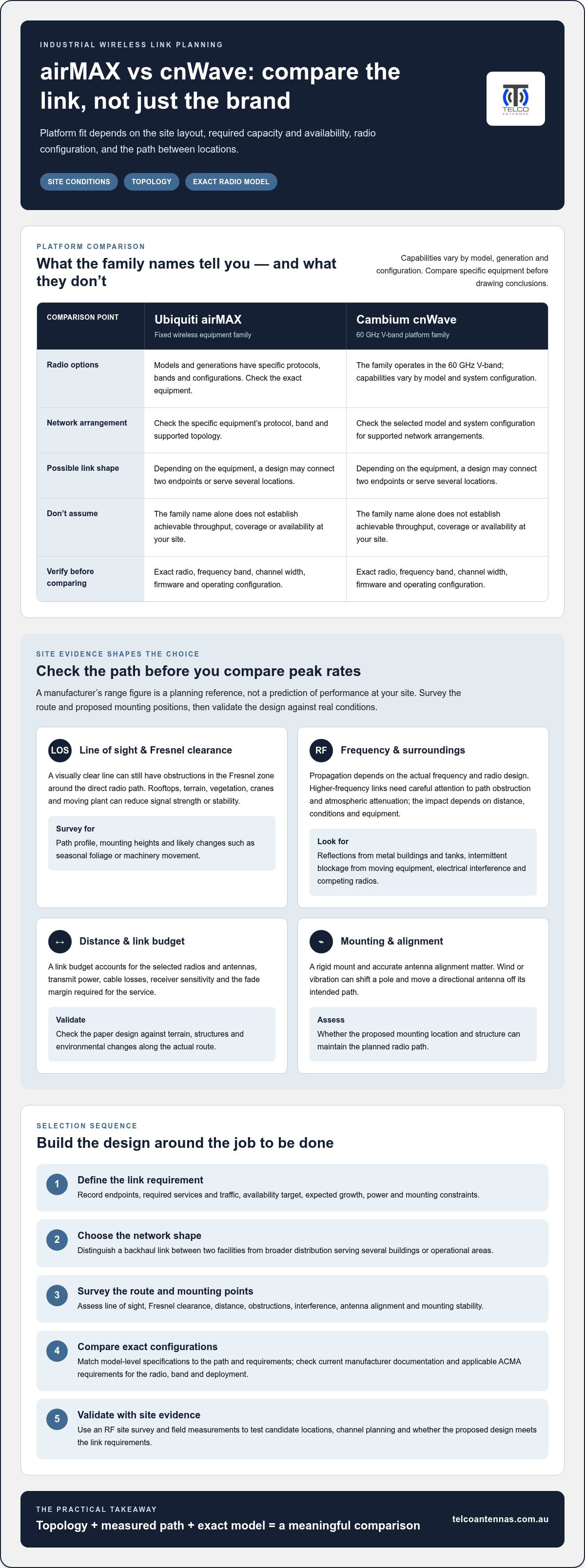
A practical workflow for selecting and designing the link
A disciplined design process turns the airMAX and cnWave comparison into a site-specific decision. Record the network need, assess the radio path, then select and validate equipment against measured conditions. For broader context on bridge planning, see this long-range wireless bridge guide.
- Define the service requirement. Identify endpoint locations, path distance, traffic direction and required throughput. Note whether traffic is continuous or intermittent, how sensitive it is to latency, the availability target and any planned expansion.
- Document site constraints. Record obstructions, possible antenna locations, mounting height and stability, available power, cable routes and exposure to weather, dust or vibration. Include access constraints that could affect installation or future maintenance.
- Survey the path and spectrum. Assess line of sight and Fresnel clearance, inspect candidate mounting points, and measure relevant RF conditions. A site survey helps test assumptions about interference and channel availability before fixing the platform and configuration.
- Build and review the link budget. Use data for the selected radio and antenna, cable losses and path conditions to estimate received signal and available fade margin. Compare the result with capacity and availability requirements, then verify the chosen band, radio and deployment against applicable ACMA requirements.
- Plan installation and validate in the field. Confirm alignment procedures, secure mounting, grounding, surge protection and cable routing. During commissioning, record signal and link-quality readings, test representative traffic, and check monitoring and fault reporting against the design requirements.
Build the requirements and survey record
Keep the findings in a shared design record so equipment selection and installation use the same assumptions. If the radio needs an elevated or purpose-designed mount, include structural and access requirements in the plan. Communication tower design is relevant where supporting infrastructure forms part of the link.
Validate the design before deployment
A successful bench setup doesn’t prove that the installed path will meet its target. Confirm the actual alignment and link budget on site, then test the traffic patterns the connection must carry. Document baseline readings and commissioning results so later troubleshooting has a useful reference point.
This workflow gives ubiquiti airmax vs cambium cnwave for industrial wireless link decisions a practical engineering basis: requirements, site evidence and validation all inform the final design. Telco Antennas provides RF site surveys and link design for project-specific assessment.
Choose the right industrial link approach with engineering support
There’s no universal winner in the ubiquiti airmax vs cambium cnwave for industrial wireless link decision. A suitable platform must match the required topology and capacity, measured radio path and operational needs of the site. Use the matrix below to identify what to assess, then verify candidate radio models and configurations against current manufacturer documentation.
A decision matrix for common industrial link scenarios
| Scenario | What to assess | Decision direction |
|---|---|---|
| Simple point-to-point | Endpoint distance, path clearance, required traffic and availability. | Either family may be a candidate if its selected models, band and configuration meet the link budget and service requirements. |
| Multiple endpoints | Number and location of endpoints, traffic flows, expansion plans and supported topology. | Compare model-level support for the intended point-to-multipoint or multi-node design; don’t infer it from the platform name. |
| Constrained path | Obstructions, mounting options, available bands and interference conditions. | Gather further site measurements. Consider a candidate only if its verified radio characteristics and proposed path support the design. |
For cnWave, assess whether the selected 60 GHz equipment and topology suit the measured path. For airMAX, compare the specific model’s band and supported configuration against the same requirements. If the path is blocked or the network needs alternate routes, account for that in the architecture rather than assuming the radio platform resolves the constraint.
Turn the comparison into a site-specific design
An RF site survey can establish path feasibility, identify mounting positions and inform radio selection. It also connects the proposed bridge hardware to practical installation details, including alignment and the structures available at each endpoint. Where elevated mounting is needed, communication tower design can form part of the wider connectivity plan.
Telco Antennas provides RF site surveys, communication tower design and point-to-point wireless bridge solutions, bringing site conditions and link requirements into one engineering assessment. This gives you a considered basis for selecting a platform, not a guarantee of range or throughput. Model specifications, configuration and applicable Australian ACMA requirements still need to suit the deployment.
To move from platform comparison to a site-specific assessment, discuss your industrial wireless link requirements with Telco Antennas.
Take the next step towards a site-ready wireless link
The choice between airMAX and cnWave depends on what the link must do, the topology it needs to support and the conditions along the radio path. Compare specific models and configurations, not platform names alone, and treat headline throughput as a starting point rather than a site performance guarantee.
For ubiquiti airmax vs cambium cnwave for industrial wireless link planning, bring requirements, RF measurements, mounting and field validation into the design process. Account for endpoint locations, traffic needs and practical site constraints before selecting hardware.
Telco Antennas supports this process with RF site surveys, point-to-point wireless bridge solutions and communication tower design. To discuss your project’s requirements and explore a site-specific approach, talk with Telco Antennas about your industrial wireless link. A design grounded in site measurements and planning gives you a practical basis for moving forward.
Frequently Asked Questions
Is Ubiquiti airMAX or Cambium cnWave better for an industrial wireless link?
Neither is a universal winner. The right fit depends on topology, radio model, frequency, path conditions and operational requirements. For the ubiquiti airmax vs cambium cnwave for industrial wireless link decision, compare the exact equipment and configuration against the site’s traffic, availability target and mounting options. Check current manufacturer specifications and assess the proposed radio path before choosing. A platform family name alone can’t establish expected performance at a particular facility.
Can airMAX and cnWave provide a point-to-point link?
Both platform families may suit point-to-point applications, but support depends on the particular radios and configuration. Identify the two endpoints, required traffic and path, then verify that the selected models support the intended link arrangement. Check current manufacturer documentation for compatible devices, operating bands, firmware and configuration requirements. Don’t assume every radio in either family has the same topology options or capacity because it carries the airMAX or cnWave name.
How far can an industrial airMAX or cnWave link reach?
There’s no reliable distance figure based on the platform name alone. Reach depends on the radio model, frequency, antenna configuration, path and Fresnel zone clearance, interference, applicable regulatory limits and the link budget. Terrain, structures or vegetation can reduce the usable path, while required availability and capacity also influence design margins. Assess the actual endpoints and check model-specific specifications rather than treating a published maximum range as a site guarantee.
Does cnWave require clear line of sight?
Plan cnWave links around a clear, well-assessed radio path. A visible line between endpoints doesn’t confirm adequate clearance, because objects near the path can intrude into the Fresnel zone and affect the signal. The clearance needed depends on the selected equipment, link geometry and installation. Survey the path, mounting heights and likely obstructions, then validate the design against current manufacturer guidance and site conditions.
Is 60 GHz suitable for an outdoor industrial wireless link?
It can be a candidate where the selected equipment’s capacity and network design suit the job and the path can be maintained. A 60 GHz link needs careful assessment of obstructions, mounting, distance and environmental attenuation. Weather effects depend on the path and conditions, so don’t assume a fixed impact. Verify the specific radio’s outdoor capabilities and specifications, then use site measurements and a link budget to assess feasibility.
What should an industrial wireless site survey measure?
A useful survey records endpoint locations and distance, path profile, line of sight and Fresnel clearance, and potential obstructions. It should also assess RF conditions and channel options, mounting positions and stability, available power, cable routing and environmental exposure. Capture traffic direction, capacity and latency needs, along with availability expectations. For an Australian deployment, include checks against the applicable ACMA requirements for the selected radio, band and configuration.
Can airMAX and cnWave be compared using advertised throughput alone?
No. Advertised throughput doesn’t show how much capacity a configured link will provide for real application traffic. Compare specific radio models, firmware, channel settings and topology, then consider usable throughput alongside latency, endpoint count and traffic patterns. Path conditions and interference also affect results. For a meaningful comparison, use current manufacturer data for equivalent configurations and validate the proposed design under representative operating conditions instead of selecting by peak figures alone.


