

Could a faster wireless bridge be the less reliable choice in a storm? A practical ubiquiti gigabeam 60ghz vs 5ghz wireless bridge rain fade comparison starts with a clear distinction: 60 GHz can support high capacity, but rain and atmospheric oxygen attenuate its signal more than they do at 5 GHz. If you’re planning a point-to-point link, that difference matters, particularly as path length and exposure to heavy rainfall increase.
Frequency alone doesn’t determine uptime. The distance between sites, line of sight, expected rain intensity, available fade margin and the specific GigaBeam model’s failover capability all affect the outcome. A 5 GHz backup may help maintain connectivity when the 60 GHz link is unavailable, but it won’t preserve the primary link’s capacity.
This article explains how rain fade affects each frequency, how to compare the trade-offs and what to assess before choosing a bridge. Use the path measurements, weather assumptions and link-budget details for your route to determine whether a 60 GHz bridge, a 5 GHz link or a failover-capable design fits your requirements.
Key Takeaways
- Include rain attenuation in a 60 GHz link budget and assess the fade margin, rather than relying on a rainfall figure alone.
- Compare rain sensitivity alongside capacity, interference exposure and line-of-sight requirements.
- Assess the actual route between sites, distinguishing observed conditions from broader assumptions about Australian weather.
- Set performance requirements, assess the path, model the link budget and identify risks before validating the design.
- RF site surveys and point-to-point bridge engineering can turn project-specific path evidence into a practical frequency choice.
What rain fade means for a Ubiquiti GigaBeam 60 GHz wireless bridge
Rain fade is the reduction in radio signal strength as precipitation absorbs and scatters energy travelling through the air between two antennas. The effect is generally more pronounced at 60 GHz than at 5 GHz, so heavy rain can reduce the signal reaching the receiving radio. The practical impact also depends on path length, alignment, obstructions and the signal margin available in the link design.
Rain sensitivity describes how precipitation affects a radio path; it doesn’t, by itself, predict whether the whole link will be reliable. That distinction is central to a useful ubiquiti gigabeam 60ghz vs 5ghz wireless bridge rain fade comparison. A short, well-aligned 60 GHz path with sufficient margin may perform adequately, while poor alignment or an obstructed path can cause problems at either frequency.
Why 60 GHz and 5 GHz respond differently to rain
Raindrops interact with radio waves, absorbing some energy and scattering some away from the intended path. The effects depend on frequency, which is why 60 GHz is generally more exposed to rain attenuation than 5 GHz. Loss can accumulate along the portion of the path affected by rain: a longer path through intense rainfall may lose more signal than a shorter path in lighter rain.
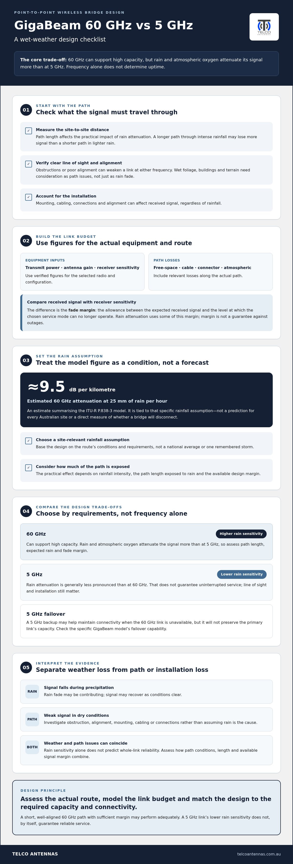
There isn’t one rain-fade value that applies to every link. Estimates summarising the ITU-R P.838-3 model put 60 GHz attenuation at about 9.5 dB per kilometre in rain of 25 mm per hour. That is a rate under a specific rainfall assumption, not a prediction for every Australian site or a direct measure of whether a bridge will disconnect. The path length exposed to that rain and the link’s design margin determine the practical effect. The broader Rain fade overview explains how precipitation affects microwave signals and why engineers consider mitigation.
What rain fade does, and doesn’t, tell you
Rain fade describes weather-related attenuation, not every cause of a weak or unstable signal. Wet foliage can obstruct or absorb radio energy. Buildings, terrain, poor alignment, unsuitable mounting and faults in cabling or connections can also reduce received signal. Assess these causes separately rather than attributing every wet-weather issue to rain.
Clear line of sight and adequate received signal are essential. A 60 GHz link’s greater sensitivity to rain doesn’t automatically make it unsuitable, just as 5 GHz’s lower rain sensitivity doesn’t guarantee uninterrupted service. Rain can use up more of a 60 GHz link’s available margin, particularly over a longer path or during intense rainfall. If a link is weak in dry conditions, investigate the path or installation; if signal drops coincide with precipitation, rain fade may be contributing. Both issues can occur at once.
- Weather-related loss: signal strength falls during precipitation and may recover as conditions clear.
- Path or installation loss: obstruction, misalignment or a connection fault can affect the link regardless of rain.
- Overall reliability: depends on how these factors combine with path length and available signal margin.
How rain attenuation changes a 60 GHz link budget
A link budget accounts for gains and losses between a transmitting radio and its receiver. It answers a practical question: after the signal travels the path, will enough power remain for the receiver to maintain the required connection? Rain attenuation adds to the path losses and uses some of the margin built into the link. It doesn’t create the same outcome for every installation.
A simplified budget adds transmit power and antenna gains, then subtracts losses such as free-space path loss, cable loss and atmospheric attenuation. The resulting received signal level is compared with the receiver’s sensitivity for the required operating mode. The difference is the fade margin. Use values for the actual equipment, configuration and path rather than relying on a generic bridge specification.
The link-budget inputs that matter in wet weather
Start with the path length and frequency. Then use the selected radio’s verified transmit power, antenna characteristics and receiver sensitivity. Include relevant feeder or connector losses, and account for clear-air propagation as well as expected rain. The rainfall assumption should reflect the site’s design conditions and the required availability, rather than a national average or a single remembered storm.
For rain attenuation, an engineer can use a recognised propagation method such as ITU-R P.838-3, which models specific attenuation against frequency and rain rate. It doesn’t, on its own, predict the link’s final availability. Its output depends on rainfall rate and the path length through rain; local weather patterns and link requirements determine the design allowance. The FCC discussion of 60 GHz wireless communications and rain attenuation also describes rain as an important consideration when engineering robust links.
More available fade margin can improve resilience to additional attenuation, provided the equipment figures, path assumptions and receiver threshold used in the calculation are accurate. Margin isn’t a guarantee against outages. It is the allowance between the expected received signal and the level at which the chosen service mode can no longer operate.
Why short and long links should not be treated alike
Rain doesn’t necessarily affect every part of a radio path equally. Signal loss depends on how much of the path is exposed to rain, the rain intensity and the frequency. A shorter link may therefore need a different rain-loss allowance from a longer one, but distance alone can’t establish whether either link is reliable. Antenna gain, alignment, obstructions and the starting signal level matter as well.
For a ubiquiti gigabeam 60ghz vs 5ghz wireless bridge rain fade comparison, calculate the budget for the exact radio and required operating mode instead of relying on headline range or capacity. GigaBeam models can differ, so use the current manufacturer datasheet for the specific model’s transmit power, antenna gain and receiver sensitivity. Telco Antennas provides RF site surveys and bridge engineering to relate those assumptions to measured path conditions and project requirements.
Ubiquiti GigaBeam 60 GHz vs 5 GHz: compare rain fade and trade-offs
The useful comparison isn’t simply “fast” versus “reliable”. A 60 GHz bridge can suit a high-capacity point-to-point link when the path and rain margin are engineered for its conditions. At 5 GHz, rain attenuation is generally lower, but interference, obstructions and equipment limits still affect performance. The ITU-R P.838 Rain Attenuation Model calculates specific rain attenuation using factors including frequency and rain rate; it doesn’t predict a complete link’s performance by itself.
Rain sensitivity: 60 GHz is generally more affected by rain attenuation than 5 GHz. The actual impact depends on rainfall along the path and the link budget.
Potential capacity: 60 GHz is used for high-capacity links, but achievable throughput depends on the exact radio, configuration and conditions. Advertised capacity isn’t a guaranteed result.
Interference exposure: 60 GHz can have lower interference exposure in some deployments. The 5 GHz band may face competing signals, but congestion depends on the site.
Line of sight: Both point-to-point frequencies need a suitable path. 60 GHz requires careful attention to clear line of sight and alignment; 5 GHz is also affected by obstructions and poor siting.
When 60 GHz may suit the link
Consider 60 GHz where high capacity is a priority and the proposed path allows precise alignment. Assess the full route, mounting stability and expected rain exposure, then model whether the link has enough margin for the required availability. A clear path is necessary, but it doesn’t remove rain attenuation or make up for inadequate received signal.
GigaBeam model details matter. The GigaBeam and GigaBeam Long-Range models are described as including a 5 GHz failover radio, while the GigaBeam Plus does not include that backup. Failover isn’t simultaneous operation, and the backup’s capacity may differ from the primary link. Use the current datasheet for the exact model and account for its operating behaviour in the resilience plan.
When a 5 GHz bridge may be the better fit
A 5 GHz bridge may be worth considering if lower rain sensitivity is a priority, particularly where a 60 GHz link budget leaves insufficient margin for the site’s weather assumptions. That doesn’t make 5 GHz the automatic choice: local interference, path length, antenna characteristics and required throughput can change the result. A clear, well-aligned route and a suitable channel plan remain important.
In a ubiquiti gigabeam 60ghz vs 5ghz wireless bridge rain fade comparison, choose by matching required throughput and acceptable availability to the assessed path and model-specific specifications. Telco Antennas supplies point-to-point wireless bridges and provides RF site surveys and bridge engineering to assess project-specific conditions.
How to assess rain fade before choosing a wireless bridge
A dependable frequency choice starts with the job the link must do, then tests whether the actual path can support it. A ubiquiti gigabeam 60ghz vs 5ghz wireless bridge rain fade comparison is useful when both options are assessed against the same throughput, availability and site requirements. Use the steps below to consider rain alongside physical and RF conditions.
What to establish before comparing frequencies
Set the required throughput, acceptable interruptions and intended link distance before comparing radios. Record what’s observed at the site separately from what’s assumed. A measured obstruction or interference source is site evidence; a broad assumption based on national weather conditions isn’t a site-specific rain profile. This long-range wireless bridge guide provides further context on path and distance considerations.
- Define the service requirement. Record the throughput the connection must support and how much disruption the application can tolerate. These requirements determine whether peak capacity or continuity during adverse conditions matters more.
- Assess the physical path. Map the endpoints and inspect line of sight, terrain, buildings, trees and other obstructions. Note mounting locations, height, structural stability and foliage that may move or become wet. Check the route from both ends; a view that appears clear from one endpoint may hide an obstruction elsewhere.
- Record environmental exposure. Separate site observations from rainfall assumptions. Identify the weather conditions relevant to the project and document the basis for the rain-rate allowance used in modelling. A national climate summary alone doesn’t establish conditions along a particular radio path.
- Model each candidate link. Use current, model-specific radio data and the assessed path to calculate expected received signal and fade margin. Include rain attenuation and other relevant losses. Compare both frequencies using consistent assumptions, not headline range or capacity claims.
- Check RF and regulatory risks, then validate. Consider interference from other RF sources, alignment tolerances, mounting movement and installation losses. Identify the applicable Australian spectrum requirements and verify them against current ACMA guidance. Record uncertainties, then validate the design against site evidence and the project’s availability target.
How to turn site conditions into a design decision
Compare the proposed margin with the service requirement, not with a generic idea of what counts as “enough”. If obstruction, interference or weather assumptions remain uncertain, state that in the assessment instead of hiding it in a single predicted signal value. An RF site survey provides measured context for planning and helps distinguish observed conditions from assumptions.
Telco Antennas provides RF site surveys and point-to-point wireless bridge engineering to assess project-specific link conditions. These services relate path evidence and link-budget assumptions to the required level of service. RF site surveys and bridge engineering are part of this project-focused assessment.
Design a reliable point-to-point bridge with project-specific RF advice
A sound frequency choice matches the link’s required capacity and resilience to evidence about the actual route. Rain exposure matters, as do path visibility, mounting stability, alignment, interference and the equipment’s verified specifications. Use the ubiquiti gigabeam 60ghz vs 5ghz wireless bridge rain fade comparison to inform the design, not replace a project-specific assessment.
What an engineering assessment can clarify
An RF site survey helps establish whether the proposed path is visible, where radios could be mounted and which physical obstructions or potential interference sources need attention. The findings inform the link budget and show which inputs are measured, which come from manufacturer data and which remain assumptions. That distinction makes the design easier to evaluate and revise as project details develop.
Telco Antennas provides RF site surveys and point-to-point wireless bridge engineering. An assessment can document candidate link designs and compare their assumptions against project requirements. It can’t remove weather effects or guarantee a particular service level. Its value is in making relevant conditions and trade-offs clearer before hardware and mounting decisions are finalised.
Moving from comparison to a workable link design
Start with the job the connection must perform. Define the required capacity and acceptable interruptions, then relate those targets to the measured or modelled path, expected weather exposure and available mounting options. If resilience matters, specify how the link should behave when conditions reduce the primary connection. Base that design on the exact equipment configuration instead of assuming every model has the same fallback capability.
Next, compare the bridge’s verified manufacturer specifications with the site evidence. Transmit power, antenna characteristics, receiver sensitivity and supported operating modes all affect whether the proposed link budget fits the path. If an input is uncertain, record it and assess its effect on the design instead of treating a headline range or throughput figure as proof of suitability.
Project-specific RF advice turns a frequency comparison into a practical design decision. Depending on the path, rainfall assumptions, capacity target and availability needs, either frequency may suit, or the design may need adjustment. Telco Antennas assesses those inputs through RF site surveys and bridge engineering, then relates the findings to suitable point-to-point wireless bridge hardware.
For a considered next step, discuss a wireless bridge solution based on your project’s path conditions and performance requirements.
Turn your link requirements into a practical design
Before selecting hardware, put the project’s operating needs into a short design brief: what the connection must carry, how much disruption is acceptable, and what’s known about the path and its weather exposure. That gives an engineering assessment a clear starting point and makes the ubiquiti gigabeam 60ghz vs 5ghz wireless bridge rain fade comparison relevant to your installation, rather than a choice based only on headline specifications.
Telco Antennas supplies point-to-point wireless bridges and provides RF site surveys and communication infrastructure engineering for project-specific assessment. This connects site evidence and link-budget assumptions with a design suited to your requirements, without treating any frequency as the automatic answer.
Discuss a point-to-point wireless bridge design and take the next step towards a link plan grounded in the conditions at your site.
Frequently Asked Questions
Does GigaBeam automatically switch to 5 GHz when rain affects the 60 GHz link?
Some GigaBeam models have a 5 GHz failover radio, but models don’t all switch bands or behave identically. The GigaBeam and GigaBeam Long-Range are described as including 5 GHz backup, while the GigaBeam Plus isn’t. Check the exact model’s current documentation and configuration for its failover behaviour. A backup connection may help maintain connectivity, but its capacity and operating characteristics can differ from the 60 GHz link.
Can a Ubiquiti GigaBeam connect to a non-Ubiquiti router or switch?
It can generally connect through Ethernet to network equipment from another manufacturer, provided the network interface and configuration are compatible. Check addressing, VLAN requirements and power supply arrangements before connecting equipment. Match the radio’s specified power method to its injector or switch port, as incompatible power delivery can prevent operation or damage equipment. The wireless bridge endpoints still need to establish a compatible radio link with one another.
Is 5 GHz Wi-Fi the same thing as a 5 GHz point-to-point bridge?
No. Both use radio energy in the 5 GHz band, but they serve different network roles. Wi-Fi usually connects client devices such as laptops and phones to an access point; a point-to-point bridge links two network locations using a radio at each end. The bridge can carry network traffic between buildings, while local Wi-Fi access points provide wireless coverage within each location. The band alone doesn’t define the equipment’s function.
Can a GigaBeam link operate through a window or glass wall?
Don’t plan an outdoor GigaBeam link through glass. A window can attenuate or reflect radio energy, and coatings or multiple panes may make the path less predictable, particularly at 60 GHz. Even if a signal appears to pass through under test conditions, changes in glass, angle or alignment can affect performance. For a fixed bridge, plan for a clear outdoor path between the radios and assess obstructions along that route.
What should I check if a wireless bridge drops during bad weather?
Compare signal and connection records from wet and dry periods, then inspect for changes that coincide with dropouts. Check whether wind has shifted a mount or alignment, whether water has entered a connector or cable, and whether wet foliage now obstructs the path. Review power, cabling and interference indicators as well. If the link remains weak in dry weather, investigate a persistent path or installation issue rather than assuming rain is the sole cause.
Do Australian spectrum rules apply to outdoor 60 GHz and 5 GHz links?
Yes. Outdoor wireless equipment in Australia must operate under the applicable ACMA requirements for its frequency band and device type. Permitted channels, power conditions and other technical rules can differ between bands and equipment classes, so don’t rely on settings or rules intended for another country. Check current ACMA guidance and the radio’s Australian compliance information before deployment, particularly if configuration options allow changes to frequency or transmit power.
Can two different GigaBeam models form a compatible wireless link?
Possibly, but don’t assume two models will pair just because they share the GigaBeam name or a frequency band. Compatibility depends on supported radio modes, firmware, channel settings and each model’s capabilities. Compare the current manufacturer documentation for both radios and confirm that their wireless modes and configuration options align. This matters especially if one model has a 5 GHz backup feature and the other does not.


