

The radio with the bigger published range may still deliver the weaker link. If you’re weighing the cambium epmp force 300 vs ubiquiti airmax ac long distance link, headline range and throughput figures won’t show how either platform will perform over your route, in the available spectrum or amid real-world interference.
Comparing specifications is a useful starting point, especially because product generations, radio settings and antenna options can make the choice less straightforward. But dependable performance comes from the whole link: clear line of sight, adequate Fresnel zone clearance, workable mounting positions and a channel that can support the required capacity in the local RF environment.
This article compares the platforms without treating theoretical figures as a promise of field performance. You’ll learn which technical factors shape a dependable point-to-point link, what to check when assessing Force 300 and airMAX AC, and what site and capacity details to gather before choosing equipment. We’ll also explain how an RF site survey assesses terrain, obstructions, interference and mounting requirements, so the design is based on the link you need to build, not just a number on a datasheet.
Key Takeaways
- Set throughput, latency, availability and future capacity requirements before narrowing down radio options.
- Compare specific Force 300 and airMAX AC model variants using current manufacturer specifications, including frequency bands, channel widths and antenna options.
- Use a link-budget assessment to understand how transmit power, antenna gain, signal losses and receiver sensitivity interact.
- For a cambium epmp force 300 vs ubiquiti airmax ac long distance link, base the decision on the surveyed path and required capacity, not a headline range figure.
- Validate the design in stages, from path analysis and equipment selection through installation and commissioning, with Australian spectrum requirements in mind.
Planning a long-distance wireless link: what the radio comparison can, and cannot, tell you
Start with the job the link must do, not the radio model. Is it a point-to-point backhaul carrying traffic between two sites, a connection to a remote building, or another fixed wireless link? The answer shapes the required capacity, link design and mounting arrangements. A link that suits basic site connectivity may not meet the demands of a busy backhaul, even if both links span the same distance.
Before comparing Force 300 with airMAX AC, define what the receiving end needs. Record the required throughput in both directions, acceptable latency, the availability the application needs and whether demand is expected to grow. These requirements help distinguish a link that merely connects from one that can carry the intended workload with operational headroom.
- Throughput: Identify the capacity required during normal and peak use.
- Availability: Consider the impact of an interruption on the connected service.
- Latency: Account for applications that depend on responsive communication.
- Growth: Allow for additional users, devices or traffic over time.
This comparison focuses on Cambium ePMP Force 300 and Ubiquiti airMAX AC. It doesn’t rank every Cambium or Ubiquiti platform, and a suitable design depends on site information. Headline range figures vary with model configuration, antenna choice, spectrum, alignment and local radio conditions. For Australian deployments, assess frequency and equipment choices against applicable ACMA requirements.
What counts as a long-distance point-to-point link?
A point-to-point link connects two fixed endpoints using directional radios and antennas, with each end aimed along the path to the other. The Point-to-point (telecommunications) overview explains how this arrangement differs from point-to-multipoint. Distance is only one measure: usable throughput and reliability depend on the quality of the radio path. Clear visual line of sight is important, but the surrounding Fresnel zone also needs adequate clearance for the signal to propagate effectively.
Why a headline range is not a design result
A manufacturer’s range figure describes a stated or idealised scenario, not the result for a particular route. Terrain, vegetation, buildings, mounting height and interference can change signal conditions between endpoints. Trees can grow into the path, and a ridge or structure may obstruct it. A clear view from one mounting position doesn’t necessarily mean the full radio path is clear.
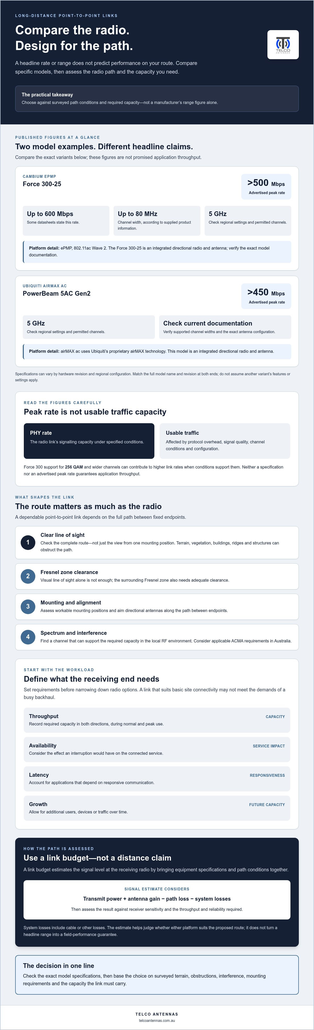
A link budget estimates the signal level at the receiving radio by accounting for transmit power, antenna gain, path loss, cable or other system losses, and receiver sensitivity. It combines equipment specifications with path conditions to estimate whether the link can support the required throughput and reliability. That’s the practical basis for judging whether either platform suits a proposed route, rather than relying on distance claims alone.
Cambium ePMP Force 300 vs airMAX AC: compare the right specifications
A fair comparison needs specific model variants, not broad platform names. The examples below pair the Cambium ePMP Force 300-25 with Ubiquiti’s PowerBeam 5AC Gen2, a model in the airMAX AC family. Specifications can vary by hardware revision and regional configuration. Use this as a starting point for checking current manufacturer documentation, not as a substitute for the relevant datasheets.
Which Force 300 and airMAX AC variants are being compared?
Both named examples are 5 GHz-class integrated radio and directional antenna units. The Force 300-25’s model suffix identifies a particular antenna configuration; the PowerBeam 5AC Gen2 is a specific airMAX AC model. Before comparing or mixing equipment, match the full model name and hardware revision at both ends of the link. Don’t assume a feature or setting described for another Force 300 or airMAX AC variant applies to these units.
Specification | Cambium ePMP Force 300-25 | Ubiquiti PowerBeam 5AC Gen2
Radio family | ePMP, 802.11ac Wave 2 | airMAX ac, Ubiquiti’s proprietary airMAX technology
Frequency class | 5 GHz; check the model’s regional settings and permitted channels | 5 GHz; check the model’s regional settings and permitted channels
Channel width | Up to 80 MHz, according to the supplied product information | Verify the supported widths against the current model documentation
Antenna/configuration | Integrated directional radio and antenna; check the exact model documentation | Integrated directional radio and antenna; check the exact model documentation
Advertised peak rate | Over 500 Mbps, with some datasheets stating up to 600 Mbps | Advertised at over 450 Mbps
Advertised rates aren’t a prediction of application throughput. A PHY rate describes the radio link’s signalling capacity under specified conditions; usable traffic capacity is affected by protocol overhead, signal quality, channel conditions and configuration. The Force 300’s support for 256 QAM and wider channels can contribute to higher link rates when conditions support them, but neither specification guarantees a particular real-world result.
Which specifications influence a fixed wireless bridge?
Channel width involves a trade-off: wider channels can carry more data, but use more spectrum and may be harder to place cleanly in a congested area. Antenna gain and polarisation affect how energy is directed and received. Transmit power is only one part of the link calculation, not a distance guarantee. Assess the combination against the path and locally available spectrum, then check applicable Australian requirements and regional device settings.
Firmware and product generation matter too. Confirm the current firmware build, supported features and compatibility for the exact hardware revisions before deployment. For general RF exposure context, the FCC Radio Frequency Safety Guidelines are a US reference, not Australian regulatory guidance.
Telco Antennas’ point-to-point wireless bridge solutions provide a practical starting point for turning radio specifications into a site-specific design.
What determines real-world range, throughput and stability?
Radio performance depends on several interacting factors, not a single range figure. A link budget brings the transmitter, antennas, propagation path and receiver together: transmit power and antenna gain add signal strength, while distance-related path loss, cable losses and obstructions reduce it. The receiving radio’s sensitivity helps determine whether the remaining signal can support a particular modulation rate. A design needs enough margin for changes in operating conditions, rather than merely reaching the receiver’s minimum sensitivity on paper.
For a cambium epmp force 300 vs ubiquiti airmax ac long distance link, the same path conditions apply to either platform. A radio may establish a connection but fail to sustain the capacity or stability the application needs if received signal quality is marginal.
Line of sight, Fresnel clearance and mounting
A visible path between antennas is only the first check. Radio energy also occupies a three-dimensional region around the direct path, known as the Fresnel zone. If terrain, a roofline or vegetation intrudes into this area, diffraction or obstruction can reduce the signal even when the endpoints can see each other. The effect depends on path geometry and frequency, so assess clearance along the route, not only at the endpoints.
Give vegetation particular attention: branches and foliage can obstruct the path, and their position or density may change over time. A path profile helps show where additional clearance is needed and whether a different mounting position or tower height could address it. Tower design should follow that assessment and account for mounting constraints and alignment, rather than relying on a general assumption that a higher antenna is always better.
Interference, channel width and link capacity
Even with a clear path, other transmitters can affect performance. Co-channel activity competes for airtime on the same frequency, while adjacent-channel signals may raise interference if they’re strong enough or poorly separated. A spectrum assessment can help identify usable channels and the local noise floor. Base channel selection on observed conditions at the link sites: activity can differ between locations and change over time.
A wider channel can provide more capacity when clean spectrum is available, but it occupies more of the band and may encounter more interference. A narrower channel may fit better where spectrum is constrained, although its capacity ceiling is lower. The radio’s modulation also matters: higher-order modulation carries more data per transmission but requires stronger signal quality relative to noise and interference. If conditions deteriorate, the link may use a less efficient rate, reducing throughput.
PHY rate is the radio’s signalling rate, while application-level throughput is the useful data delivered after overhead, retransmissions and other protocol costs. This distinction is essential when comparing advertised figures. IEEE develops technical standards used across wireless communications; its wireless communication standards provide a foundation, but vendor-specific radio protocols and configuration still affect how a deployed link operates.
For Australian installations, verify the permitted band, channel and power settings, and that the equipment configuration meets current ACMA requirements. A site assessment can combine the path profile, interference findings and equipment settings into a design based on the actual operating environment.
How to choose between Force 300 and airMAX AC for your link
Neither platform is a universal winner for a long-distance bridge. The right choice depends on the service the link must carry, what the surveyed path allows and how the equipment will fit into the wider network. Use this workflow to narrow the options before committing to a design.
Use the link’s requirements to narrow the choice
- Define the service. Record the traffic the link will carry, the required usable throughput in each direction, acceptable latency and the impact of an outage. Include expected growth so the design isn’t sized only for today’s load.
- Document the endpoints and path. Note endpoint locations, proposed path length, terrain, and any buildings or vegetation along the route. A path survey can show whether line of sight and Fresnel clearance are workable, and whether a different mounting position is needed.
- Assess spectrum at the sites. Check which channels are usable and whether co-channel or adjacent-channel activity could affect performance. A theoretical channel option has little value if the local RF environment makes it unsuitable.
- Check mounting and physical constraints. Identify practical antenna positions, mounting heights, access and alignment requirements. If a suitable position depends on a tower or other support, include it in the design instead of leaving it as a later installation detail.
- Compare verified model capabilities. Match the exact Force 300 or airMAX AC variants against the required capacity, channel options, antenna configuration and regional settings. Use current manufacturer documentation for the specific hardware revision; don’t transfer features from another model in the family.
This sequence makes the cambium epmp force 300 vs ubiquiti airmax ac long distance link decision more practical: it tests each platform against the same path and service requirements instead of relying on a headline specification. If one option appears to meet the capacity target only under ideal signal conditions, assess whether the design has enough margin for the expected operating environment.
Account for expansion, compatibility and operations
Consider how the selected radio will fit the existing network. Check the management workflow, firmware support and the skills or processes available to operate and troubleshoot the link. If the network already uses equipment from one ecosystem, that may simplify administration, but it doesn’t by itself prove that the radio is the better technical fit.
For future expansion, look beyond peak rate. Consider whether the proposed link can accommodate additional traffic, whether spectrum availability could constrain a later capacity increase, and whether an upgrade would require changes at both endpoints. Don’t assume Cambium and Ubiquiti radios will interoperate as a matched wireless bridge; verify compatibility for the exact equipment and configuration.
Let the evidence guide the recommendation. A clear path and suitable spectrum may make either option viable; difficult mounting, interference or specific network-management needs may favour one configuration over another. For more planning context, review long-range wireless bridge planning considerations before finalising the design.
Validate the long-distance link design before deployment
A platform comparison narrows the options, but it doesn’t validate a route. Before installing either radio, plan a sequence of checks: survey the sites, analyse the path, select equipment against the findings, install and align the bridge, then commission it against the service requirements. This can reveal problems a specification sheet can’t, such as an obstructed path or a mounting position that can’t be built as planned.
What an RF site survey should establish
An RF site survey brings together the physical and radio conditions at both endpoints. It should record endpoint coordinates and proposed path length, examine the terrain profile, and assess line of sight and Fresnel-zone clearance along the route. The survey also considers vegetation, buildings and other obstructions, interference, and practical antenna placement at each end.
These findings inform equipment selection and the assumptions behind the link budget. For example, if the proposed mounting point leaves part of the path obstructed, the design may need a different position or support structure before a radio is chosen. If the spectrum assessment finds interference on a preferred channel, that should shape channel planning and capacity expectations. An RF site survey turns those conditions into inputs for an engineering-led bridge design, rather than leaving them to be discovered during installation.
From link design to commissioning
Once the path and equipment are settled, install to the planned positions and alignment. Commissioning should include configuring both radios consistently, aligning the antennas, and measuring signal and link performance against the design requirements. If results differ from expectations, check alignment, configuration and local radio conditions before treating the link as ready for service.
Record the installed model and hardware revision, firmware and radio settings, antenna positions, alignment readings and measured baseline performance. This gives network operators a reference if performance changes later, and helps distinguish a new fault from the link’s original operating conditions.
Set mounting height using the path profile and required clearance, and choose a support that suits the installation. Where the route calls for elevated or specialised mounting, communication tower design considerations can inform the structural planning. Avoid increasing height by guesswork; the design should account for the path and mounting requirements together.
For an Australian deployment, verify current spectrum, power and equipment requirements against ACMA guidance before configuring and commissioning the radios. Requirements can depend on the equipment and operating settings, so use current guidance rather than assuming a configuration used elsewhere applies locally.
Telco Antennas provides wireless bridge solutions, RF site surveys and communication tower design for project-specific link planning.
Turn your link requirements into a buildable plan
Turn the comparison into a project brief: identify the endpoints, the service the link needs to carry, and any known constraints on the route or mounting. That gives the design a practical basis and keeps equipment selection tied to the deployment, rather than a general preference for one platform.
If you’re still weighing the cambium epmp force 300 vs ubiquiti airmax ac long distance link, a site-specific assessment can help answer what datasheets can’t: how the path, local RF conditions and support structure fit together. Telco Antennas can bring RF site survey findings and communication tower design into point-to-point wireless bridge planning, shaping a design around the project’s physical requirements.
Discuss your point-to-point wireless bridge requirements with Telco Antennas to take the next step towards a considered link design. With the right site information, you can move forward with a clearer view of the equipment and installation the connection needs.
Frequently Asked Questions
Are Cambium ePMP Force 300 and Ubiquiti airMAX AC radios interoperable?
Generally, don’t assume they can form a wireless bridge together. The Force 300 uses Cambium’s ePMP platform, while airMAX AC uses Ubiquiti’s proprietary airMAX protocol, so matching frequency bands or Ethernet connections doesn’t establish compatibility over the air. For a new link, plan for compatible radios at both ends and check the manufacturer’s documentation for the exact models and firmware. A mixed-brand network may still connect through standard wired Ethernet.
Does a 5 GHz point-to-point link work over a long distance?
Yes, a 5 GHz link can serve a long route if the equipment, antenna system and path provide adequate received signal and capacity. Suitability depends on the actual distance, terrain, frequency conditions, antenna placement and link budget, rather than the band alone. For example, a clear route between elevated sites may be more practical than a shorter path with a ridge in the way. Model the route before selecting equipment.
Can a wireless bridge work without direct line of sight?
Sometimes a link can operate with partial obstruction, but performance and reliability may be reduced, so don’t treat it as a dependable design assumption. A ridge, building or dense vegetation can block or weaken the path. Reflections or diffraction may allow a connection in some conditions, but they don’t guarantee usable capacity. Check the full path profile and Fresnel clearance. If an obstruction can’t be cleared, assess an alternative route or mounting position.
How much throughput can a long-distance wireless link deliver?
There’s no single throughput figure for a long-distance link. The result depends on the selected radio and channel configuration, received signal quality, interference, traffic direction and protocol overhead. A datasheet’s peak PHY rate isn’t the same as application data available to users. Set a required usable capacity first, then assess whether the proposed link can meet it under expected conditions. Measure traffic performance during commissioning and compare it with the design target.
Is a higher-gain antenna always better for a point-to-point link?
No. Higher gain can concentrate energy into a narrower beam, which may help on a suitable route but makes accurate alignment more demanding. The antenna also needs to suit the radio, polarisation, mounting position and path. Increased antenna gain affects the overall transmitted power calculation, so the configured system must remain within applicable Australian requirements. Choose gain from the link budget and installation conditions, not as a standalone way to increase range.
What Australian spectrum requirements apply to a fixed wireless link?
Requirements depend on the frequency band, device and operating configuration. Before deployment, check current ACMA guidance for the relevant band and whether operation is subject to class-licence conditions or requires another authorisation. Confirm that the equipment’s Australian configuration, channel and transmit settings are appropriate; a setting available in another country may not be suitable here. Keep a record of the settings used so the installed link can be reviewed against current requirements.
How can interference be identified before installing a wireless bridge?
Use an RF site survey to inspect the spectrum at both proposed endpoints, ideally from positions representative of the final antenna locations. A spectrum analyser or the radio’s scanning tools can help reveal occupied channels, elevated noise and activity that varies over time. Compare observations from both ends, since a channel that appears clear at one site may be busy at the other. Use the findings to inform channel selection and capacity expectations before installation.


