

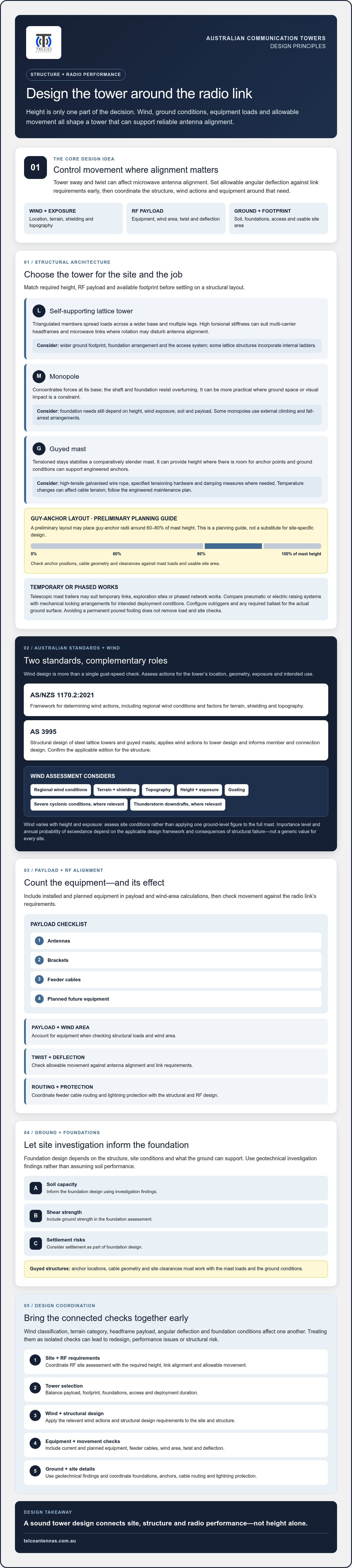
What if a communication tower were designed around the movement its radio link can tolerate, rather than height alone? For microwave links, tower sway and twist can affect antenna alignment, so deflection limits need to inform structural decisions from the outset. Wind actions, terrain exposure and equipment loads all shape that response.
It’s understandable to find the design process difficult to coordinate. Wind classifications, terrain categories, antenna headframe payloads, allowable angular deflection and foundation conditions are connected. Treating them as separate checks can lead to redesign, performance issues or structural risk.
This guide explains key principles behind communication tower design in Australia. You’ll learn how AS/NZS 1170.2:2021 informs wind loading and how AS 3995 applies to steel lattice towers and masts, alongside the factors that guide tower selection and RF payload calculations. We’ll also cover geotechnical and guy-anchor considerations, feeder cable routing and lightning protection, so you can see how structural engineering and radio performance fit together in a practical design process.
Key Takeaways
- Match tower type to required height, RF payload and available site footprint before settling on a structural layout.
- For communication tower design, assess wind actions under AS/NZS 1170.2:2021 and confirm the applicable AS 3995 edition for the structure.
- Use geotechnical investigation findings to inform foundation design, including soil capacity, shear strength and settlement risks.
- Include antennas, brackets, feeder cables and planned future equipment in payload and wind-area calculations, then check twist and deflection against link requirements.
- Coordinate RF site assessment, structural design and equipment planning early to reduce clashes between radio performance and tower requirements.
Communication Tower Design: Selecting the Optimal Structural Architecture
Tower selection affects more than structural capacity. It sets the compound footprint, foundation arrangement, access requirements and the amount of RF equipment the structure can support. A self-supporting lattice tower may suit a site needing a rigid, high-capacity headframe, while a monopole can be more practical where ground space or visual impact is a constraint. Guyed masts can provide height with a relatively light mast structure, but need room for anchor points and suitable ground conditions. An overview of radio mast and tower types clarifies the main structural distinctions.
Self-Supporting Lattice Towers vs. Monopole Structures
A lattice tower spreads loads across a wider base and multiple legs. A monopole concentrates forces at its base and relies on its shaft and foundation to resist overturning. The lattice’s triangulated members can provide high torsional stiffness, an advantage for multi-carrier headframes and microwave links where rotation can disturb antenna alignment. A monopole generally uses a smaller ground footprint, but its foundation requirements still depend on height, wind exposure, soil and payload. Compare steel use and foundation volume for the actual design rather than assuming either from tower height alone.
Maintenance access is another selection factor. Some lattice structures incorporate internal ladders, while monopoles may use external climbing and fall-arrest arrangements. The chosen system needs to suit the structure, inspection approach and safe access requirements.
Guyed Masts and Tensioned Cable Engineering
Guyed masts use tensioned stays to stabilise a comparatively slender mast, making them an option where land is available and ground conditions can support engineered anchors. A preliminary layout may allow for guy-anchor radii around 60 to 80 per cent of mast height, but this is a planning guide, not a substitute for site-specific design. Check anchor positions, cable geometry and clearances against the mast’s loads and the usable site area.
Guy systems require suitable high-tensile galvanised wire rope, correctly specified tensioning hardware and damping measures where needed. Temperature changes can affect cable tension, so inspection and re-tensioning should follow the engineered maintenance plan rather than an assumed universal schedule.
Rapid Deployment Mobile Mast Trailers
For temporary links, exploration sites or phased network works, telescopic mast trailers can provide an alternative to a permanent tower. Compare pneumatic or electric raising systems with mechanical locking arrangements for the intended deployment conditions, and confirm that the mast can be secured as designed. Configure outriggers and any required ballast for stability on the actual ground surface. A trailer avoids a permanent poured footing, but it doesn’t remove the need for load and site checks.
In communication tower design, the right architecture balances RF alignment, payload, footprint, foundations, access and deployment duration for the site.
Australian Standards and Wind Loading Design Fundamentals
Wind design isn’t a single gust-speed check. A tower must be assessed for the wind actions appropriate to its location, geometry, exposure and intended use, including gusting and, where relevant, severe cyclonic conditions and thunderstorm downdrafts. In Australian communication tower design, AS/NZS 1170.2:2021 provides the framework for determining wind actions, while AS 3995 addresses the structural design of steel lattice towers and guyed masts. The standards have different, complementary roles.
Applying the tower and wind standards
AS/NZS 1170.2 establishes the process for deriving design wind actions, including regional wind conditions and factors for terrain, shielding and topography. AS 3995 applies those actions to the tower structure and informs supporting member and connection design. The importance level and annual probability of exceedance depend on the applicable design framework and the consequences of structural failure, so they shouldn’t be selected using a generic value for every telecommunications site.
Wind speed also varies with height and exposure. Engineers assess the structure’s height and site conditions rather than applying one ground-level figure to the entire mast. Confirm the applicable editions and project requirements, including relevant National Construction Code provisions.
Wind region, terrain and topography
The wind region sets an important starting point, including whether cyclonic conditions apply. Terrain categories reflect the roughness of the surrounding landscape, from open water or exposed terrain to built-up areas with substantial obstructions. Shielding may affect wind exposure, but it needs to be justified by actual surroundings rather than assumed from nearby buildings that could change or provide incomplete protection.
Elevated sites need particular care. A hilltop, ridge or escarpment can increase wind speeds locally, so the topographic factor must reflect the landform and tower position. Use the resulting design pressure to assess the tower and its equipment, not just the bare structure.
Vortex shedding and dynamic response
Slender cylindrical monopoles can experience crosswind oscillation as wind flows around the shaft. The shedding frequency relates to wind speed and mast diameter. If it approaches a natural frequency of the structure, vibration and fatigue demand may increase. Engineers assess resonance risk using dynamic analysis, including the Strouhal relationship, rather than relying on a general rule of thumb. Helical strakes or tuned mass dampers may be considered where analysis shows they’re appropriate, but neither is a universal fix.
Wind actions also need to be coordinated with foundation assumptions. Geotechnical findings inform how those actions transfer into the ground, while the tower assessment determines the demands the foundation must resist. To align RF requirements with structural decisions, explore communication tower design support.
Geotechnical Engineering, Soil Mechanics, and Tower Foundations
A tower’s foundation has to transfer structural loads into ground that may vary across the site and with changing moisture conditions. Wind creates overturning moments and lateral shear as well as compression, while guyed structures and some foundation arrangements also introduce uplift forces. A footing that appears adequate for the tower’s downward weight may still be unsuitable if it can’t resist these combined actions or control settlement.
Geotechnical investigation and soil classification
For sound communication tower design, investigate the ground at the proposed foundation and guy-anchor locations, not just elsewhere on the property. A geotechnical engineer can select suitable methods, which may include boreholes and dynamic cone penetrometer testing, to establish the soil profile and identify weak or variable layers. The investigation should inform bearing capacity, shear strength and settlement assessment.
Expansive clay needs particular attention because seasonal moisture changes can cause ground movement. Determine how reactive the soil is and whether drainage or site conditions could worsen that movement. Record groundwater depth too: a high water table may affect excavation, construction and the foundation’s resistance to buoyancy. The investigation scope should suit the site risks and proposed structure.
Choosing a foundation system
Foundation type follows from the tower loads, ground profile and construction constraints. A broad mass concrete pad may use its weight and dimensions to resist overturning, but its performance depends on soil strength, embedment and the applied wind loads. Where near-surface material is weak, a reinforced bored pier may transfer vertical and lateral forces into deeper, more competent strata. On suitable bedrock, engineered rock anchors can provide a load path into the rock, subject to checks on rock quality, bond capacity and installation.
These are design options, not interchangeable prescriptions. The engineer must check bearing, sliding, overturning, uplift and settlement for the relevant load combinations. Guy anchors also need their own geotechnical assessment because their capacity depends on the ground around each anchor, not simply the mast foundation.
Corrosion protection below ground
Buried steel can deteriorate where soil chemistry and moisture create corrosive conditions. Soil resistivity, pH and sulfate testing can help characterise exposure and guide protection choices. Depending on the results, the design may specify suitable coatings, concrete cover to reinforcement or corrosion-resistant details for hold-down bolts and other embedded steel.
Cathodic protection, including sacrificial anodes, may be considered for vulnerable buried metal, but it needs to be designed for the material and site conditions. Coating systems should also be selected for the intended environment and installation, rather than assumed suitable by product type alone. Coordinating geotechnical findings with structural and corrosion design reduces the risk of choosing a foundation that works on paper but not in the ground.
RF Payload Calculations, Twist and Tilt Tolerances, and Feeder Management
A tower’s RF payload affects both its structural demand and the performance of the network it supports. Antennas, dishes, brackets, radio units and feeder cables add deadweight, but they also present area to the wind. A structurally adequate tower can still be a poor link support if its headframe rotates or deflects beyond the antenna system’s alignment tolerance.
Calculating antenna drag and projected area
Effective Projected Area (EPA) helps represent the wind exposure of mounted equipment. Use manufacturer data for each antenna’s relevant orientation and wind direction, including front, side and, where supplied, slant values. Then account for the complete installation: panel arrays, parabolic dishes, remote radio units, mounts, cable ladders and feeder runs. Their positions matter because closely spaced equipment can interact with airflow.
Model the installed payload, not just the initial build. Include reserved expansion equipment where it’s part of the project plan, so future additions don’t exceed the assessed capacity. For cellular deployments, include MIMO antennas in the headframe load schedule, using verified equipment data rather than generic assumptions.
Twist, sway and alignment for microwave links
For a narrow-beam link, small angular movements can shift the antenna’s main lobe away from the receiving dish. Compare predicted tower and headframe rotation under the relevant serviceability wind conditions with the antenna’s beamwidth and link alignment requirements. A 3 dB beamwidth describes the angular range over which received power falls by 3 dB from its peak. It’s useful context, but not by itself an allowable tower deflection. The acceptable limit depends on the link budget, frequency, distance and equipment.
There’s no universal twist limit that suits every installation. A value such as 0.5 degrees should only be used if project analysis confirms it meets the structural and RF criteria. Assess torsional stiffness at the headframe as well as overall tower sway. Stiffening or anti-twist elements may be considered if calculations identify excessive movement. For link applications, see point-to-point wireless bridges.
Feeder routing and lightning coordination
Feeder design must balance mechanical support with signal performance. Include internal or external cable ladders in the wind-load assessment, secure cable runs to limit movement, and follow the cable manufacturer’s minimum bend radius. For LMR-400 coaxial cable, use the applicable product data and connector requirements. Tight bends or poorly supported runs can damage the cable or compromise the RF path.
Coordinate the tower’s lightning protection and earthing design with the structural and cable layout. Down conductors, bonding and earthing arrangements need to follow the applicable standards and site design, rather than an assumed configuration. To align antenna payload and feeder requirements with a tower assessment, discuss communication tower design.
The Engineering Workflow: From RF Site Survey to Turnkey Commissioning
A reliable deployment moves through linked decisions, from confirming the radio path to validating the installed link. Findings at each stage can affect the next: terrain may change the required antenna height, which changes structural loads, foundation requirements and equipment access. Treating communication tower design as an iterative process helps identify those dependencies before fabrication and installation are underway.
Phase 1: RF assessment and site planning
Start with the link objective, frequency, proposed equipment and site constraints. RF propagation modelling estimates the path, while an on-ground RF site survey checks terrain, obstructions, interference and practical antenna positions. Together, these inputs help establish the antenna centreline height needed for the intended link. A map-based line of sight alone may not capture local obstructions or spectrum conditions.
Before committing to a layout, identify planning approvals and other site-specific requirements. Depending on the proposal, these may include council planning assessment, aviation obstacle marking or lighting considerations, and environmental overlays. Confirm the applicable process with the relevant authorities. If a separate mobile coverage issue is identified, a Cel-Fi GO mobile signal booster may be considered as an equipment option, subject to suitability for the site and network.
Phase 2: Structural design and fabrication
Once the RF requirements and site conditions are established, the structural package can coordinate tower geometry, headframe positions, payload and access. Fabrication drawings should identify members, connections and assembly orientation clearly, with calculations and material specifications checked against the project design. Communicate changes to antenna count or mounting arrangement, as equipment added after structural assessment can alter both weight and wind demand.
Steelwork protection should suit the exposure environment and project specification. Where hot-dip galvanising is specified, confirm the coating requirements and applicable standard, including AS/NZS 4680 where relevant, with the designer and fabricator. Inspect completed components and resolve fabrication or coating issues before transport and erection.
Phase 3: Construction, installation and handover
Build the foundation to the issued design and verify the required concrete strength or curing criteria before applying erection loads. During assembly, follow the approved erection sequence and use the specified fasteners and tightening procedure. Calibrated tools may be required where the connection specification calls for them. Record checks and deviations so they can be reviewed against the design.
After the structure is erected, riggers can install and align antennas, secure feeders and complete bonding and earthing work to the project requirements. Commissioning should include antenna alignment and RF checks, such as sweep testing where applicable, followed by records of the final configuration and test results. Telco Antennas offers RF site surveys and communication tower design, as well as hardware such as MIMO antennas and LMR-400 coaxial cables for telecommunications infrastructure.
Plan Your Next Tower Project with Confidence
Reliable infrastructure depends on decisions that work together: tower type and wind design must suit the site, foundations must match ground conditions, and the RF payload must stay within both structural and link-alignment tolerances. A coordinated workflow from field survey through commissioning helps keep those requirements connected rather than treating them as separate tasks.
That’s the practical value of integrated communication tower design. Telco Antennas offers RF site surveys and communication tower design, alongside telecommunications hardware including mobile signal boosters, MIMO antennas and specialised RF cabling. Aligning these elements early can help clarify the requirements for your site and the equipment it needs to support.
If you’re planning a new installation or assessing an existing link, contact Telco Antennas about communication tower design and RF site surveys.
Frequently Asked Questions
What is the primary difference between AS 3995 and AS/NZS 1170.2 for tower design?
AS/NZS 1170.2:2021 sets out how to determine wind actions on structures, while AS 3995 covers the structural design of steel lattice towers and guyed masts. In practice, engineers establish the site-specific wind demands under AS/NZS 1170.2, then apply the relevant tower design provisions to assess members and connections. For communication tower design, confirm the applicable editions and project requirements rather than assuming a standard applies unchanged to every structure.
How do I calculate the total Effective Projected Area (EPA) for my antenna payload?
Total EPA is determined by assessing each item’s wind-facing area and applicable drag data, then combining the values for the relevant wind direction. Use manufacturer data for antennas, dishes, radio units and mounting hardware, accounting for front, side or other specified orientations. Include cable ladders and feeder runs, and allow for planned future equipment. The final calculation should follow the applicable wind design method, not a simple sum of equipment dimensions.
When is a self-supporting lattice tower preferred over a guyed mast structure?
A self-supporting lattice tower is often suitable where the site has limited space for guy anchors or where the installation needs a rigid structure for a dense equipment headframe. Its broader base and triangulated members can provide useful torsional stiffness for multiple antennas and microwave links. A guyed mast may suit a site with room for anchor points and appropriate ground conditions. Compare the footprint, payload, access and foundation demands for the actual site.
What degree of angular deflection is acceptable for point-to-point microwave dishes?
There is no single angular deflection limit that applies to every microwave dish or link. The acceptable movement depends on factors such as operating frequency, antenna beamwidth, link distance and the required link margin. The 3 dB beamwidth can help describe antenna directivity, but it isn’t automatically the allowable tower rotation. Have the structural response under serviceability wind conditions checked against the link’s alignment requirements and equipment data.
Can a mobile telescopic mast trailer substitute for a permanent communication tower?
A telescopic mast trailer can serve as a temporary alternative for applications such as a short-term link, exploration activity or phased deployment, provided its capacity and operating conditions suit the equipment and site. It doesn’t automatically replace a permanent tower: height, payload, wind exposure, stability, ground surface and deployment duration all need assessment. Check the mast’s securing and stabilisation arrangements, and confirm whether the installation’s planning or operational requirements allow a mobile structure.
How does ground soil classification affect the overall cost of tower foundations?
Soil classification influences foundation type, dimensions and construction requirements, which in turn affect the scope and resources needed for the foundation. Strong, stable ground may support a different solution from weak, variable or moisture-reactive soil, where deeper foundations or additional investigation may be needed. Groundwater, settlement risk and the loads from wind and guy anchors also matter. A geotechnical investigation provides the design inputs needed to compare suitable options and estimate project costs.
What corrosion protection standards are mandatory for Australian telecommunications towers?
There isn’t one corrosion protection standard that applies universally to every tower component and site condition. Protection requirements depend on the material, exposure and project specification. Where hot-dip galvanising is specified, AS/NZS 4680 is a relevant standard for coatings on fabricated ferrous articles. Engineers may also specify suitable coatings, concrete cover or other measures for buried steel and reinforcement. Confirm the applicable standards and design requirements for the specific structure and environment.


