
Your DC-DC boost unit isn't overheating simply because of harsh summer conditions; it's almost certainly starving for current. If your dish drops offline during heavy transmit peaks while the potted casing turns scalding to touch, effective starlink 12v conversion step up converter overheating troubleshooting begins at the battery terminals, not the heatsink.
It's infuriating to watch your connection reset right when throughput peaks, leaving you guessing whether the dish, your cabling, or the converter itself is failing. Generic advice often suggests strapping on a cooling fan, but treating surface temperatures does nothing to address the severe input voltage sag driving up amperage inside the module.
This technical guide will help you pinpoint the exact electrical and mechanical faults driving thermal runaway, calculate actual current demands, and execute lasting wiring corrections. We will walk through a step-by-step diagnostic sequence to build a resilient, efficient 12V DC power architecture that withstands heavy transmission loads and demanding environments.
Key Takeaways
- Master the core principles of starlink 12v conversion step up converter overheating troubleshooting by identifying how input voltage sag forces severe current spikes and thermal runaway.
- Execute a load-based diagnostic sequence to separate DC supply voltage drop from internal component failure without guesswork.
- Evaluate thermal derating curves to understand why sealed epoxy bricks fail in high ambient heat compared to industrial finned converters.
- Apply practical conductor sizing and conductive heatsink mounting techniques to lower operating temperatures and prevent thermal throttling.
- Build a reliable DC power architecture engineered to withstand demanding off-grid battery charge fluctuations across harsh environments.
Understanding Why Starlink 12V Step-Up Converters Generate Excessive Heat
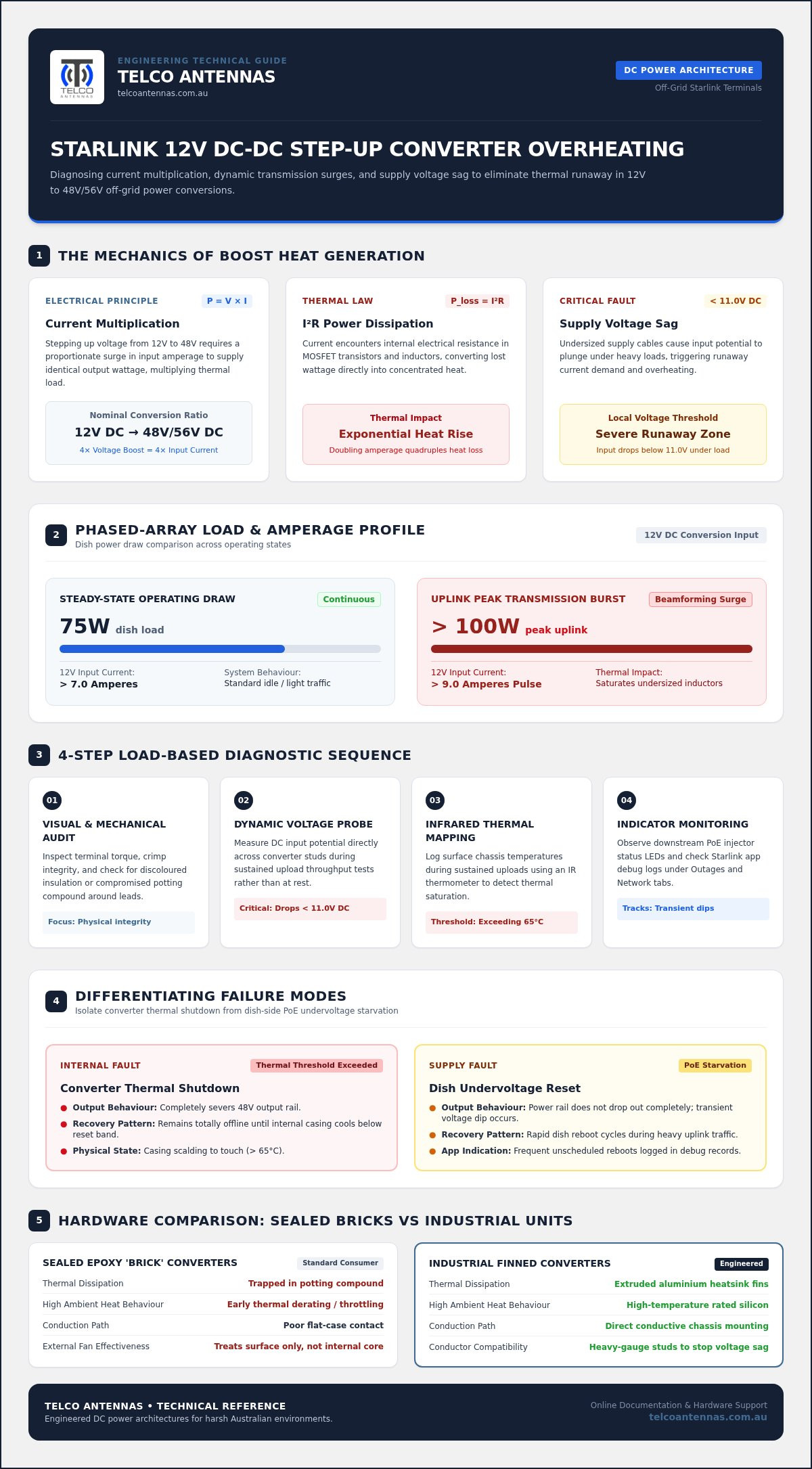
Running an off-grid Starlink terminal directly from a battery bank requires transforming a nominal 12V direct current into the 48V or 56V demanded by the dish or Power over Ethernet (PoE) injector. Many operators assume extreme operating temperatures stem solely from poor ventilation or blistering Australian ambient heat. In truth, understanding fundamental boost converter principles reveals that thermal generation is primarily driven by current multiplication. Stepping up voltage requires a proportionate surge in input amperage to deliver identical output wattage.
The Mechanics of DC-DC Voltage Boost and Current Multiplication
Basic electrical law dictates that power equals voltage multiplied by current. When boosting a nominal 12V input up to 48V to power a Standard dish running a 75W load, the converter must pull over 7A continuously on the 12V side, even before factoring in conversion inefficiencies. This intense current flow encounters internal electrical resistance within the converter's MOSFET switching transistors and inductors, converting lost wattage straight into heat via $I^2R$ power dissipation. Inside sealed, epoxy-potted aluminium casings, this heat concentrates quickly without substantial conduction paths.
Phased-Array Transmit Spikes versus Steady-State Power Draw
A dish does not pull power in a steady, flat line. While idle periods draw relatively modest current, active beamforming and satellite handshakes trigger momentary uplink transmission bursts pushing total draw past 100W. Each transmit spike forces the 12V input circuit to deliver brief pulses exceeding 9A. These frequent, sharp current spikes saturate undersized inductor cores and overload the switching stages. When undertaking starlink 12v conversion step up converter overheating troubleshooting, identifying these continuous dynamic surges explains why surface fans alone cannot resolve an internal electrical saturation issue.
Systematic Diagnostic Steps to Pinpoint Converter Thermal Failure
Diagnosing an overheating module requires methodical bench and in-situ electrical testing rather than relying on guesswork. Thermal stress directly accelerates known failure mechanisms in power electronics, degrading internal semiconductor junctions long before total component breakdown occurs. To isolate whether your system is suffering from external wiring resistance or internal converter fatigue, work through this targeted test sequence:
- Visual and mechanical audit: Check terminal torque and crimp integrity. Inspect for discoloured insulation or compromised potting compound around lead entries.
- Dynamic voltage probe: Measure direct DC input potential at the converter terminals during peak network throughput rather than at rest.
- Infrared thermal mapping: Log surface temperatures across the converter chassis during sustained upload runs using an infrared thermometer. Casings exceeding 65°C indicate critical thermal saturation.
- Status indicator monitoring: Observe fault LED patterns on your downstream PoE injector to track transient voltage dips.
Measuring Real-Time Voltage Sag Under Heavy Uplink Load
A battery monitor display showing 12.8V at the central busbar often hides severe local voltage sag. Resistance in undersized supply cables, inline fuses, and distribution switches causes measurable drops over distance. Place your digital multimeter probes directly across the step-up converter's DC input studs while running a sustained uplink speed test. If input potential plunges below 11.0V DC under load, current demands escalate rapidly, doubling conduction losses and driving the unit into runaway heating.
Differentiating Thermal Shutdown from Power over Ethernet Starvation
Accurate starlink 12v conversion step up converter overheating troubleshooting requires distinguishing between an internal module cut-out and dish-side undervoltage resets. When a boost converter hits its thermal threshold, it completely severs 48V output until the internal casing drops below its reset band. In contrast, PoE starvation causes rapid dish reboot cycles without completely killing power output.
Review the Starlink application debug data under the "Outages" and "Network" tabs. If the dish reports frequent unscheduled reboots while input voltage holds steady, examine your passive injection cabling. If power vanishes completely while the converter housing is scalding to touch, your boost hardware has hit safety limits. Upgrading your install with rugged Starlink aftermarket power conversion hardware ensures continuous stability by maintaining conversion headroom under punishing operating loads.
Converter Sizing and Thermal Derating: Cheap Bricks versus Industrial Hardware
Most budget step-up supplies sold online are compact, potted resin bricks originally engineered for intermittent auxiliary lighting rather than continuous high-draw telecommunications. These modules encapsulate internal circuitry in solid epoxy inside a smooth cast-aluminium shell. While potting provides moisture resistance, it acts as a thermal blanket that traps heat around the switching stages. Off-grid systems demand industrial-grade DC-DC converters equipped with deep extruded cooling fins, heavy-duty terminal blocks, and active thermal management.
Selecting appropriate hardware requires looking past theoretical nameplate ratings. Evaluating tested hardware configurations referenced in professional Starlink accessories solutions highlights why commercial-grade conversion gear avoids the thermal saturation issues typical of unbranded imports.
Understanding Thermal Derating Curves in Enclosed Environments
Manufacturer current ratings almost universally assume an open-air testing environment at 25°C. Inside a sealed vehicle canopy or unventilated caravan battery compartment under the Australian sun, internal ambient air routinely climbs past 55°C. At these temperatures, thermal derating curves take effect. A converter rated for 10A derates heavily as ambient heat climbs, frequently cutting safe continuous capacity down to 5A. When conducting starlink 12v conversion step up converter overheating troubleshooting, running a module beyond its derated capacity is the most common reason for unexpected thermal shutdown.
Efficiency Ratings and Resulting Heat Dissipation Calculations
The gap between an 88% efficient budget converter and a 95% industrial unit sounds minor, but it represents more than double the wasted heat. When a Gen 3 dish pulls 100W during heavy transmission, an 88% efficient converter converts nearly 14W directly into heat within the housing. Sealed in epoxy, this trapped energy causes internal junction temperatures to spike rapidly. In contrast, a 95% efficient unit using low-resistance MOSFETs and synchronous rectification loses barely 5W, allowing exterior fins to easily shed the thermal load into surrounding air.
Practical Step-by-Step Solutions to Eliminate Converter Overheating
Eliminating thermal failures requires fixing the physical wiring pathway and thermal conduction path simultaneously. Effective starlink 12v conversion step up converter overheating troubleshooting focuses on treating root electrical bottlenecks rather than masking the symptoms with small external fans.
Apply these four targeted hardware corrections to lower operating temperatures and restore reliable throughput:
- Minimise run length: Place the converter within 1.5 metres of the primary DC distribution hub.
- Replace blade fuses: Swap standard automotive spade fuses for high-integrity MIDI fuses or heavy-duty circuit breakers to cut high-resistance contact points.
- Upgrade distribution connectors: Ditch generic barrel plugs or push-fit terminals in favour of genuine Anderson connectors capable of handling continuous high-amperage draw without heating up.
- Apply conductive heatsink mounting: Bolt the converter directly to flat aluminium canopy framework using a silicone-based thermal interface paste.
Upgrading Cable Gauge to Minimise Input Circuit Resistance
Undersized copper conductors create immediate resistance when subjected to high primary current. For an off-grid installation powering a Standard dish, standard automotive 2.5 mm² wire is inadequate over any run exceeding one metre. We recommend installing heavy-gauge DC cabling, stepping up to a minimum of 6 mm² (approx. 9 to 10 AWG) for runs under two metres, and 10 mm² for longer distribution lines. Strip the ends cleanly, apply anti-corrosion paste, and terminate them into heavy-duty tinned copper lugs using a calibrated hydraulic crimper to guarantee zero voltage drop across the joint.
Mechanical Heatsinking, Enclosure Venting, and Conductive Mounting
Surface dissipation on cast-alloy converter shells relies on direct contact conduction. Avoid mounting hardware onto timber backing boards, carpeted canopy linings, or marine ply, as these materials trap radiant heat. Instead, bolt the converter directly onto an unpainted aluminium mounting plate or external canopy wall. Spread a uniform 0.5 mm layer of thermal paste across the module's flat base before securing the mounting fasteners. This conductive bridge transfers heat away from the core electronics and uses your vehicle's metallic bodywork as a broad heatsink.
For installations situated inside sealed utility boxes or unventilated gullwing canopies, install a low-draw, magnetic-levitation 12V exhaust fan ducted directly above the converter's cooling fins. If you are experiencing persistent thermal throttling across challenging environments, explore engineered Starlink aftermarket power conversion solutions built to withstand high continuous loads under severe conditions.
Designing a Resilient Starlink 12V Power Architecture for Extreme Conditions
Executing thorough starlink 12v conversion step up converter overheating troubleshooting means stepping back to assess your overall DC electrical topology. A stable system must handle continuous dynamic loads while absorbing the real-world voltage swings of off-grid auxiliary systems. Between alternator charging spikes, solar charge controller bulk absorption phases peaking past 14.4V, and late-night lithium discharge curves dipping near 12V, your step-up hardware needs broad input tolerance and robust protection to prevent thermal runaways.
Selecting High-Reliability Aftermarket Hardware for Remote Operations
Field reliability hinges on purpose-built hardware capable of enduring sustained vibration and high ambient heat. Rather than deploying light-duty consumer modules, choose industrial-grade aftermarket conversion gear featuring wide-range input stages (typically 9V to 36V DC) and integrated over-current, over-voltage, and short-circuit protection.
Galvanically isolated converters offer superior electrical protection compared to cheaper non-isolated topologies. By separating input and output ground planes, isolated units prevent stray ground loops, block alternator noise, and shield sensitive phased-array circuitry from chassis-borne electrical transients. Look for hardware housed in anodised aluminium extrusions rated to at least IP65. This ensures total protection against fine bulldust while high-density finning sheds heat without exposing delicate circuit boards to the elements.
Integrating DC Starlink Systems with Comprehensive Off-Grid Comms
A resilient installation balances total operational load against primary battery and solar storage. While running direct DC eliminates inverter conversion penalties of 10% to 15%, drawing between 25W on a Mini dish and 100W on a Standard dish still requires adequate auxiliary battery capacity and well-ventilated electronics enclosures.
Broadband satellite setups deliver exceptional remote bandwidth, but establishing total off-grid connectivity often requires layered redundancy. In heavy tree canopies, deep valleys, or sudden cloudbursts, overhead satellite paths can drop momentarily. Pairing your DC Starlink setup with a permanent cellular booster creates an autonomous, fault-tolerant network. As detailed in our Cel-Fi GO signal boosters guide, combining low-draw mobile signal enhancement with ruggedised satellite conversion hardware ensures mission-critical communications remain dependable across every Australian journey.
Building Thermal Resilience into Your 12V Starlink Setup
Resolving DC boost failures comes down to sound electrical fundamentals. As our starlink 12v conversion step up converter overheating troubleshooting process demonstrates, runaway heat is rarely just an airflow issue. It is almost always driven by supply voltage sag forcing aggressive current multiplication, combined with the thermal limits of budget potted electronics. Upgrading your primary DC conductor sizing, eliminating high-resistance connections, and mounting modules directly onto conductive aluminium structures will protect your hardware from mid-transmission dropouts.
Engineering your off-grid power distribution correctly ensures unbroken broadband across demanding remote terrain. Backed by Australian telecommunications engineering expertise since 2008, Telco Antennas supplies field-tested infrastructure and power gear built to survive extreme ambient heat. When you're ready to eliminate thermal cut-outs for good, explore professional Starlink aftermarket power conversion solutions at Telco Antennas and keep your remote communications running with total confidence.
Frequently Asked Questions
Why does my Starlink 12V step-up converter get extremely hot to touch?
Your converter gets hot because boosting 12V DC up to 48V or 56V quadruples the input amperage, generating intense internal heat through MOSFET switching losses and resistance. When input voltage sags below 11.5V due to undersized supply wiring, the unit draws even higher current to maintain the required wattage. Solid resin potting compounds also trap this thermal energy within the casing rather than shedding it efficiently.
Can a hot step-up converter cause my Starlink dish to reboot intermittently?
Yes, excessive operating temperatures directly trigger abrupt dish reboots. As the step-up converter overheats, internal components hit their thermal protection limits and momentarily drop voltage output or shut off entirely. This drops the Power over Ethernet supply below the operating threshold of the phased-array terminal. The dish immediately starves for power, restarts its boot cycle, and begins renegotiating its satellite uplink from scratch.
What wire gauge should I run to my Starlink 12V boost converter?
You should run a minimum of 6 mm² (approx. 9 to 10 AWG) automotive cable for short DC runs under two metres from your battery distribution busbar. If your cable run extends between two and four metres, upgrade the conductor sizing to 10 mm² to keep line resistance minimal. Correct sizing keeps total input voltage drop under 2% during full 100W transmission spikes, preventing thermal runaway.
Is an unbranded step-up converter safe for continuous Starlink operation?
Unbranded converters are generally not safe for continuous operation because they lack adequate thermal dissipation and proper safety protections. Most generic modules use basic aluminium shells filled with potting resin, which cannot dissipate the continuous 7A to 9A input current drawn by a Standard dish. Engaging in practical starlink 12v conversion step up converter overheating troubleshooting usually leads to replacing these budget bricks with industrial, finned DC-DC units built with wide input ranges.
What happens if my step-up converter exceeds its maximum operating temperature?
Exceeding the maximum rated operating temperature will cause the converter to enter thermal shutdown or experience permanent semiconductor breakdown. Most hardware incorporates internal thermal cut-outs between 65°C and 85°C. When triggered, the converter cuts DC output entirely until internal temperatures fall. Sustained heat below the cut-off point also degrades electrolytic smoothing capacitors rapidly, introducing high ripple voltage that damages downstream PoE injectors and dish circuitry.
Can I mount my Starlink step-up converter inside an enclosed vehicle canopy?
You can mount it inside an enclosed canopy, provided you bolt the converter directly onto an unpainted aluminium surface using thermal paste to facilitate heat conduction. Vehicle canopies in Australia routinely reach ambient temperatures above 50°C in direct sunlight, severely reducing natural convection. In tight or poorly ventilated spaces, you should install a small, low-draw 12V brushless exhaust fan directly over the cooling fins to prevent ambient heat trapping.
How do I know if my Starlink dropout is caused by heat or voltage drop?
You can diagnose the root cause by measuring input voltage with a multimeter during active transmission while logging chassis temperature. If terminal voltage holds above 12.0V DC but the unit casing exceeds 65°C before dropping power, thermal cut-off is your primary issue. If the dish reboots while the converter feels relatively cool, severe line voltage sag or downstream PoE drop is starving the dish before heat builds up.


