

Erecting the tallest pole possible won't automatically fix weak cellular reception; in practice, selecting an antenna mast for mobile booster systems is an RF isolation calculation rather than a simple elevation exercise. When an approved repeater system repeatedly reduces gain or drops out entirely, it's tempting to think that greater height is the universal cure. However, unchecked elevation often introduces severe coaxial signal attenuation and feedback oscillation between your donor and service antennas, leaving the repeater operating well below its potential.
You shouldn't have to compromise between achieving clean line-of-sight and maintaining electrical stability. This guide shows you how to engineer, select, and install the correct mast hardware to maximise mobile booster performance and maintain adequate separation across Australia. We will break down the functional trade-offs between fascia mounts, heavy-duty aluminium tripods, and telescopic masts, alongside the structural wind-loading standards required to keep your installation completely secure.
Key Takeaways
- Engineering the right antenna mast for mobile booster systems prevents feedback oscillation by securing adequate physical isolation between donor and service antennas.
- Compare the mechanical strengths of fixed fascia brackets, aluminium tripods, and telescopic masts to match your structure type and terrain.
- Calculate the critical trade-off between elevation and signal attenuation, protecting your link margin with matched 50-ohm low-loss coaxial cabling.
- Ensure structural stability by selecting mounting hardware rated to withstand site-specific Australian wind loading standards under AS/NZS 1170.2:2021.
- Follow a systematic installation protocol that integrates electrical bonding to AS/NZS 3000 Wiring Rules with precise carrier base station alignment.
Why Mobile Booster Systems Demand a Dedicated Antenna Mast
In cellular deployments, an antenna mast is not merely a conduit for height; it serves as an engineered structural support designed to maintain precise RF alignment under dynamic environmental loads. Standard television aerials can tolerate lightweight, flexible tubing because broadcast signals are broad-beam and strictly receive-only. By contrast, deploying an antenna mast for mobile booster hardware requires rigid two-way link stability. If structural flex alters the donor antenna's bearing by even a few degrees, reception drops sharply. When approved cellular repeaters detect rapid variations in signal quality or phase caused by mast movement, internal self-protection algorithms automatically throttle down amplification to protect the carrier network.
The Mechanical Demands of High-Gain Directional Antennas
Directional units such as Log-Periodic Dipole Arrays (LPDAs) and parabolic grid antennas deliver substantial passive gain, but they do so through narrow horizontal beamwidths, often tighter than 30 degrees. This narrow beam demands absolute rotational stability. Mast torsional twist during wind events rotates the antenna off-axis, creating rapid drops in uplink and downlink signal quality. In telecommunications engineering, as outlined in technical references on radio masts and towers, support structures must resist dynamic wind-load deflection. Inadequate brackets or thin-walled tubing permit micro-movements that induce carrier tower handover faults, forcing the booster into oscillation protection modes.
Clearing Ground Clutter and Establishing Clear Line-of-Sight
Achieving stable cellular coverage requires clearing the first Fresnel zone of physical obstructions. Local clutter, such as dense gum trees, neighbouring structures, and corrugated iron shed roofs, scatters high-frequency cellular bands and causes severe signal attenuation. Selecting the right antenna mast for mobile booster setups provides the elevation needed to capture a clean receive signal level (RSL) with minimal multipath distortion. By clearing boundary fences, roof ridges, and metal cladding, you prevent signal diffraction and deliver an unobstructed RF path back to the carrier base station.
Antenna Separation: Engineering Mast Height to Eliminate Feedback Loops
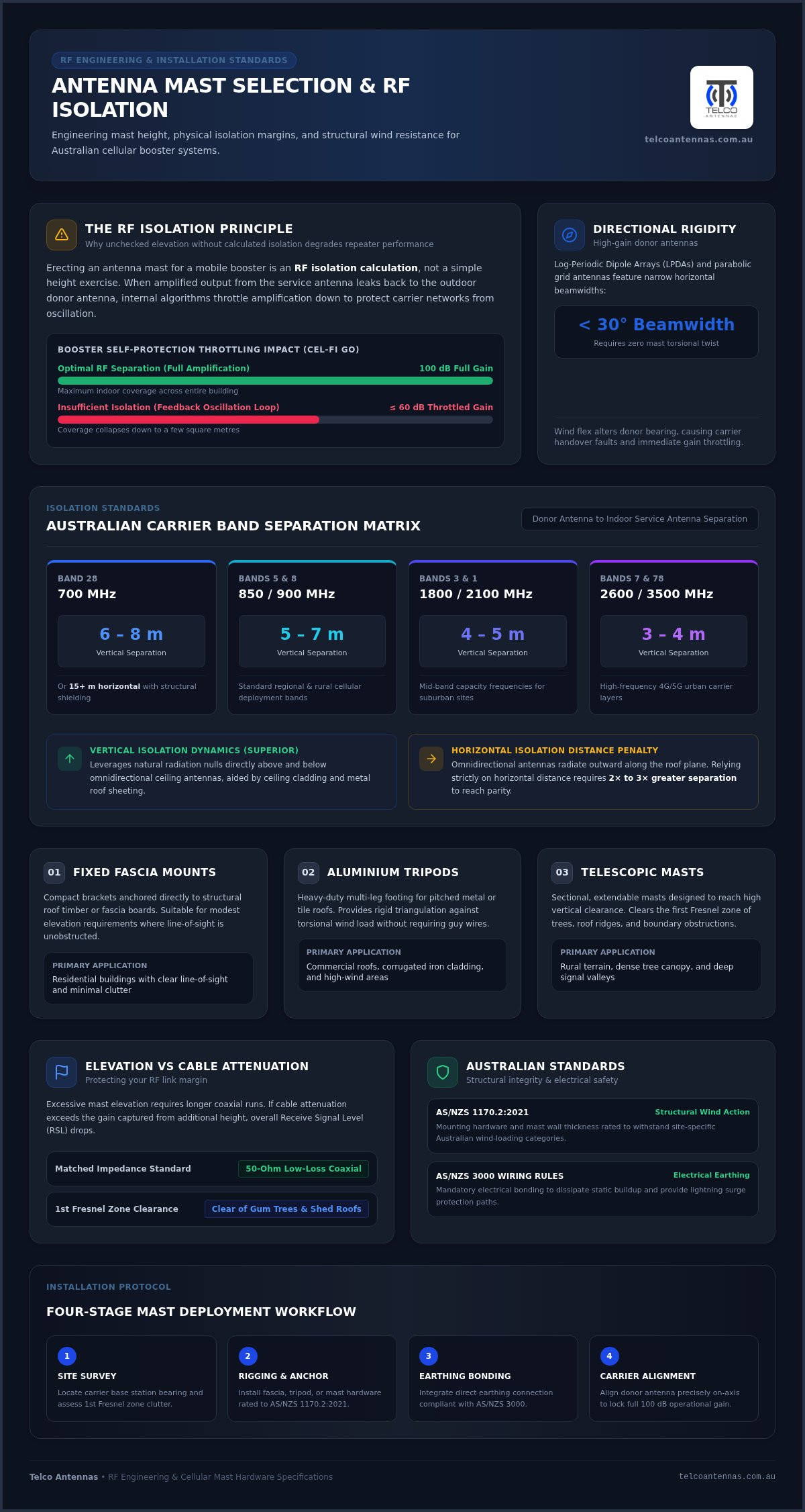
RF oscillation occurs when the amplified output from an internal service antenna leaks back into the external donor antenna, creating an electronic feedback loop. When isolation is insufficient, modern cellular hardware actively protects the network by attenuating its own output. Deploying a purpose-built antenna mast for mobile booster systems provides the physical separation required to prevent this loop. Without proper height, a carrier-approved Cel-Fi GO booster will automatically throttle down from its full potential 100dB operational gain to safe, low-power states, drastically shrinking indoor coverage.
The following separation matrix demonstrates the isolation margins required across standard Australian carrier bands:
- 700 MHz (Band 28): 6 to 8 metres vertical separation (or 15+ metres horizontal with structural shielding)
- 850 / 900 MHz (Bands 5 & 8): 5 to 7 metres vertical separation
- 1800 / 2100 MHz (Bands 3 & 1): 4 to 5 metres vertical separation
- 2600 / 3500 MHz (Bands 7 & 78): 3 to 4 metres vertical separation
Vertical vs Horizontal Isolation Dynamics
Vertical separation delivers vastly superior path loss compared to horizontal distance. Most omnidirectional ceiling antennas radiate outward horizontally, creating natural null zones directly above and below their ground plane. Installing your outdoor donor antenna high above the roofline leverages these radiation nulls, alongside the physical barrier of ceiling cladding and roof sheeting. If you rely solely on horizontal separation across a single roof plane, you must double or triple the separation distance to achieve equivalent decibel isolation.
Diagnosing Booster Throttling and System Warnings
Booster status LEDs or mobile management apps indicate feedback state errors through warning flags or reduced operational gain figures. When gain collapses from 100dB down to 60dB or lower, indoor coverage can shrink from an entire structure down to a few square metres. Relocating indoor antennas often yields marginal improvements; elevating the donor unit via a rigid antenna mast for mobile booster installations is the definitive physical remedy. If your site layout presents challenging isolation constraints, consulting the RF engineering team at Telco Antennas can assist in calculating exact link budgets before you anchor hardware.
Selecting the Right Mast Type for Australian Structural Deployments
Every structural deployment demands a calculated choice of hardware based on the building profile, local terrain, and the required antenna elevation. Standard domestic dwellings often need minimal vertical clearance to breach a roofline, whereas sprawling rural homesteads and agricultural compounds require significant elevation to clear surrounding topography. For operations requiring mobility, resources sectors frequently deploy fully mobile telescopic mast trailers to establish temporary base communications without civil works. Choosing an antenna mast for mobile booster systems requires matching these situational factors to three primary hardware categories.
Fixed Fascia and Parapet Mounts for Domestic Premises
Heavy-Duty Telescopic Masts and Guyed Systems
For rural homesteads surrounded by mature timber or undulating hills, telescopic push-up masts deliver elevations ranging from 6 to 15 metres. Constructed from high-tensile aluminium or hot-dip galvanised steel, these multi-section poles extend sequentially and secure via heavy-duty collar clamps. Elevated installations require three-way or four-way guy-wire configurations spaced at 120-degree or 90-degree radial intervals. Using stainless steel turnbuckles and pre-formed wire grips ensures exact tensioning. Periodic maintenance is essential across arid Australian regions, where airborne grit can foul collar friction mechanisms over time.
Freestanding Towers and Non-Penetrating Roof Tripods
Where guy wires are impractical or structural penetrations are prohibited, non-penetrating aluminium tripods and freestanding lattice sections offer practical alternatives. Engineered lattice configurations draw on standard communication tower design principles to support multiple directional arrays without external bracing. In leased commercial spaces with flat metal-deck or concrete roofs, lightweight aluminium tripods weighted with dense concrete pavers deliver high lateral stability. Thick UV-stabilised rubber matting placed beneath the ballast trays protects Colorbond steel finishes from mechanical abrasion and galvanic corrosion.
Balancing Mast Height with Coaxial Cable Attenuation and Wind Loads
Every metre of vertical elevation gained introduces additional coaxial cable length, forcing an engineering trade-off between captured signal strength and transmission loss. While an antenna mast for mobile booster systems can secure line-of-sight over obstacles, using improper cabling negates those reception gains before the signal reaches the repeater. Domestic 75-ohm television cabling (such as RG6) must never be used in cellular systems; it creates a severe impedance mismatch with 50-ohm telecommunications equipment, causing high Voltage Standing Wave Ratios (VSWR) and signal reflections that destabilise the booster.
To preserve your link margin across long vertical drops, select your transmission line based on signal attenuation per 10 metres across common Australian operational frequencies:
- RG58 (Thin diameter): ~4.5 dB loss at 700 MHz; ~7.8 dB loss at 1800 MHz; ~9.9 dB loss at 2600 MHz
- LMR-240 (Mid-grade): ~2.5 dB loss at 700 MHz; ~4.2 dB loss at 1800 MHz; ~5.2 dB loss at 2600 MHz
- LMR-400 (Solid-core low-loss): ~1.2 dB loss at 700 MHz; ~2.1 dB loss at 1800 MHz; ~2.6 dB loss at 2600 MHz
- 1/2" Corrugated Copper (Commercial Heliax): ~0.7 dB loss at 700 MHz; ~1.1 dB loss at 1800 MHz; ~1.4 dB loss at 2600 MHz
Coaxial Cable Selection: The Critical Feeder Link
RG58 cable should never exceed two to three metres; running 15 metres of RG58 down a telescopic mast erases more than 11 dB of signal in mid-band frequencies, cancelling the antenna's passive gain entirely. For standard structural masts up to 12 metres, solid-core 50-ohm LMR-400 coaxial cable is the industry baseline, preserving critical decibels across extended runs. On commercial towers exceeding 20 metres, low-attenuation half-inch corrugated copper Heliax lines provide the required shielding and low insertion loss to preserve reception margins.
Calculating Wind Load and Structural Survival Ratings
Structural survival depends on calculating the total Effective Wind Area (EWA), which combines the surface drag of the mast pole with the mounted antenna hardware. Wide solid panel radomes create high sail areas, whereas cast-aluminium grid antennas allow airflow to pass straight through, reducing torsional strain. Compact directional MIMO antennas present significantly lower wind resistance, making them ideal for high-exposure mounts. All structural fixings must comply with AS/NZS 1170.2:2021 wind-loading actions, utilising M10 or M12 coach screws embedded into structural timber framing, or high-tensile bolts secured through steel purlins. If you require assistance calculating site-specific wind actions or link budgets, explore industrial masts and low-loss cabling at Telco Antennas to match your operational demands.
Installation Protocol: Rigging, Earthing, and Carrier Alignment
A dependable field deployment follows a disciplined five-stage commissioning sequence: structural mounting, cable dressing, electrical earthing, carrier alignment, and diagnostic testing. Before handling equipment on-site, evaluate physical clearances. Maintain strict exclusion zones around overhead mains powerlines; an aluminium mast contacting high-voltage wiring carries fatal electrical risks. Installers must deploy certified fall-arrest harnesses, static lines, and ladder securing equipment when working at heights to ensure complete personal safety throughout the build.
Rigging and Weatherproofing Feeder Assemblies
Feeder lines require firm mechanical support to prevent vibration fatigue. Secure cabling along the mast using UV-stabilised composite cleats or marine-grade stainless steel ties spaced at 500mm intervals. At the base of the mast, form a generous drip loop before feeding the line into the external conduit or wall seal, preventing wind-driven rainwater from tracking into the structure. Seal every outdoor coaxial connector using a multi-layer process: apply an initial wrap of electrical tape, follow with self-amalgamating butyl tape to create a vulcanised moisture barrier, and cover with UV-rated vinyl tape to prevent solar breakdown.
Lightning Protection and Electrical Earthing Requirements
Elevated support poles capture static buildup and attract transient atmospheric charges during electrical storms. Under AS/NZS 3000:2018 Wiring Rules, an antenna mast for mobile booster hardware must be earthed directly to the site ground electrode using heavy-gauge stranded copper conductor. Protect internal booster electronics by integrating an inline gas discharge tube surge arrestor where the coaxial run meets the building boundary. Bond the arrestor housing to the main earth busbar to direct high-voltage transient spikes into the ground before they reach indoor hardware.
Precision Azimuth Alignment and System Commissioning
Directional donor antennas cannot be aligned through visual estimations alone. Rotate the donor antenna across its bearing in controlled five-degree increments, pausing 30 to 45 seconds at each step to allow carrier telemetry to refresh. Commission the system by tracking live diagnostic metrics: prioritize Signal-to-Interference-plus-Noise Ratio (SINR) alongside Reference Signal Received Power (RSRP). Securing high SINR values prevents base station contention and delivers maximum operational stability. For complex site geometries or custom mast requirements, consult Telco Antennas for specialised hardware selection and RF system design.
Maximise Cellular Stability with an Engineered Support System
Achieving stable voice and high-throughput data requires treating physical infrastructure with the same engineering rigour as the radio electronics. Selecting the right antenna mast for mobile booster systems resolves the core challenge of RF feedback oscillation, allowing your repeater to sustain its maximum amplification without self-throttling. Balancing this vertical separation against coaxial transmission line losses and local wind-loading dynamics ensures your equipment delivers optimal reception through severe weather events.
Telco Antennas has operated as Australian telecommunications and RF engineering specialists since 2008, supplying structurally certified mounting hardware built to endure extreme inland conditions. From ACMA-approved repeaters to matched 50-ohm LMR-400 coaxial cabling and heavy-duty aluminium tripods, our hardware systems integrate seamlessly to preserve link margins. If you are preparing an installation, explore heavy-duty antenna masts and RF mounting hardware at Telco Antennas to engineer a reliable, high-performance cellular link today.
Frequently Asked Questions
How high should my antenna mast be for a mobile phone booster?
Your mast should be high enough to establish clear line-of-sight to the base station and secure at least 6 metres of vertical isolation above the indoor antenna. For standard residential properties, a 1.8 to 3-metre roof-mounted pole is typically sufficient. However, rural sites with dense tree lines often require 6 to 12-metre telescopic masts. Keep in mind that building-mounted masts exceeding 5 metres require local planning approval under federal low-impact regulations.
Can I mount my mobile booster antenna to an existing television aerial pole?
Mounting to an existing television pole is not recommended. Most TV aerial mounts use thin-walled aluminium tubing designed solely for light, omnidirectional loads. High-gain cellular directional antennas experience significant wind resistance, causing domestic TV poles to bend or twist off-axis. Deploying a dedicated antenna mast for mobile booster systems ensures the structural rigidity needed to maintain a locked RF bearing during heavy winds.
What is the minimum physical separation needed between donor and service antennas?
Aim for a minimum of 6 to 8 metres of vertical separation or at least 15 metres of horizontal separation. Vertical spacing is vastly more effective because it takes advantage of the natural radiation nulls located directly above and below ceiling antennas. Insufficient separation forces the booster's internal software to throttle amplification to prevent destructive feedback loops, severely limiting indoor coverage.
Do I need guy wires for a roof-mounted telescopic antenna mast?
Yes, any multi-section telescopic mast extending more than 3 metres above its highest structural roof bracket requires guy-wire support. Use a three-way guy configuration positioned at 120-degree radial intervals to resist multidirectional wind loads. Non-guyed installations introduce high leverage forces against the building fascia or framing, risking structural damage and severe antenna deflection during storms.
Will a taller mast always improve my mobile signal reception?
Not necessarily. While additional elevation can clear ground clutter, every additional metre of height requires longer coaxial cable runs that introduce signal loss. If the signal gain achieved by raising the antenna is smaller than the attenuation introduced by the longer feeder line, overall system performance decreases. Mast height must always be balanced against the decibel loss per metre of your chosen cable.
What type of coaxial cable should be run down an antenna mast?
Always run 50-ohm low-loss coaxial cabling, such as solid-core LMR-400, down your mast. Never use domestic 75-ohm television cabling like RG6; the impedance mismatch creates signal reflections that degrade booster amplification. Thin cables like RG58 should also be avoided on structural runs, as high signal attenuation above 1800 MHz erases the passive gain provided by your donor antenna.
Is an external antenna mast required to be earthed in Australia?
Yes, external antenna masts must be electrically bonded to the property's main earthing system in accordance with AS/NZS 3000:2018 Wiring Rules. Earthing dissipates dangerous static charges and mitigates transient voltages caused by nearby lightning activity. Installing a properly grounded inline coaxial surge arrestor where the transmission line enters the building envelope is also required to protect internal repeater hardware.


