

For many regional Australians, the transition to Starlink gen 3 isn't just a simple hardware upgrade; it's a complete rethink of how remote connectivity integrates with existing site infrastructure. You've likely realised that while the promise of Wi-Fi 6 and improved throughput is compelling, the reality of proprietary cabling and a higher power draw presents significant hurdles for standard 12V setups and traditional Aussie roof types. It's frustrating when a "plug-and-play" solution requires a complex workaround just to keep your batteries from draining overnight or to secure a stable mount against high wind loads.
This technical reference provides the engineering clarity you need to deploy the Gen 3 system reliably across the Australian landscape, focusing on mechanical stability and electrical efficiency. We'll bypass the marketing flair to examine the hardware's actual performance metrics in high-temperature environments and off-grid scenarios. You'll gain a clear understanding of the specific power requirements for DC conversion, the practical benefits of the modular router architecture, and the validated mounting strategies required to ensure long-term structural integrity. This guide delivers a professional roadmap for integrating this hardware into a robust, high-performance communication kit that doesn't compromise your power budget.
Key Takeaways
- Understand the mechanical shift from actuated motors to the manual, fixed-position phased array design to ensure precise alignment and long-term structural stability.
- Identify efficient 12V power conversion strategies to manage the increased power draw of the starlink gen 3 system without the parasitic losses of standard AC inverters.
- Learn how to secure the non-actuated hardware against high wind loads using professional mounting solutions tailored for Australian Colorbond and tile roof profiles.
- Optimise local network distribution by leveraging the integrated Wi-Fi 6 architecture and dual Ethernet ports for professional-grade site integration.
- Minimise signal attenuation over extended cable runs by utilising low-loss LMR-400 coaxial cabling and the precision alignment tools within the Starlink application.
Understanding the Starlink Gen 3 (V4) Standard Kit
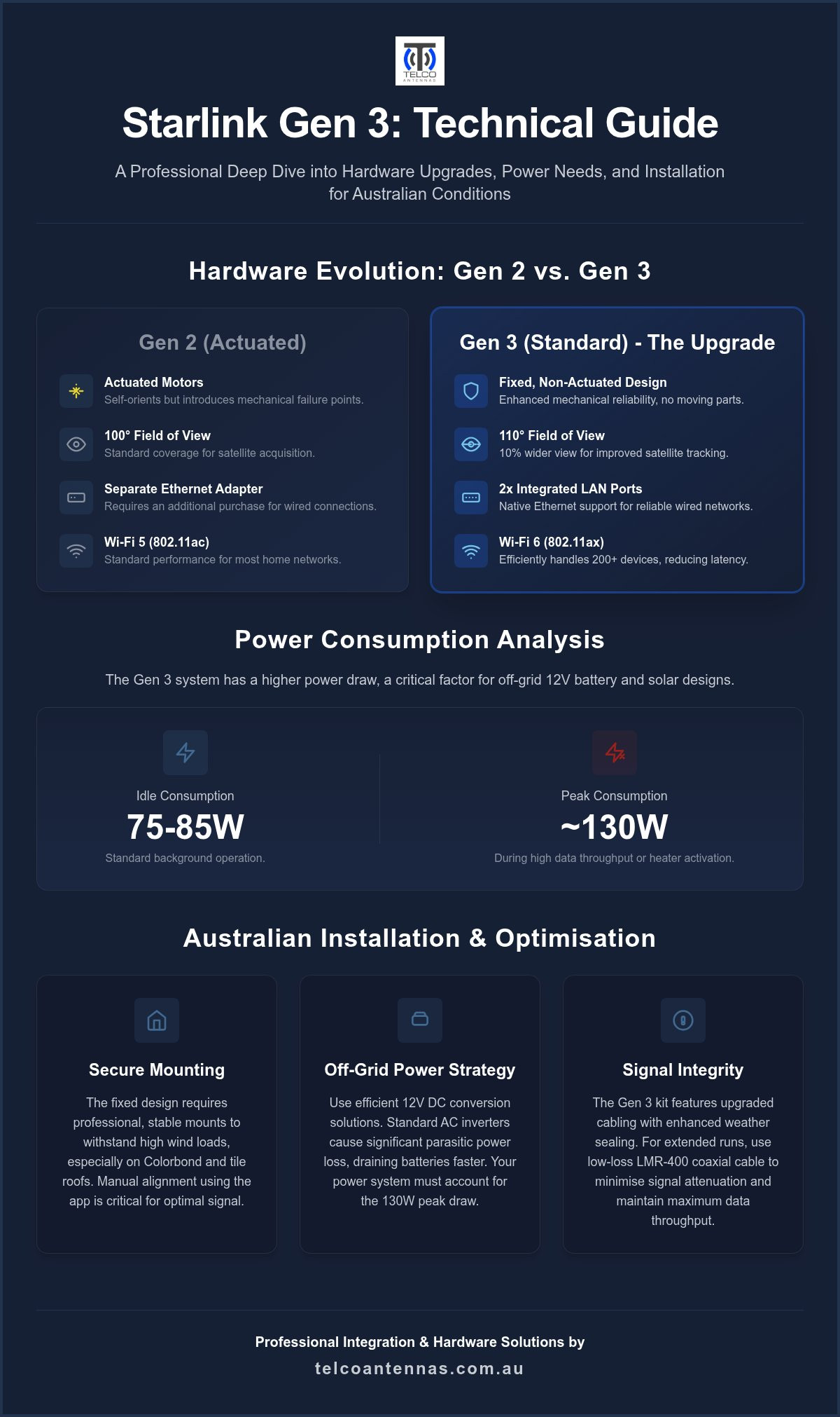
The arrival of the starlink gen 3 hardware marks a pivot from consumer-grade gadgets to professional-tier infrastructure. This iteration, often referred to as the V4, is a non-actuated, fixed-position phased array antenna. Unlike previous versions that utilised internal motors to self-orient, the Gen 3 relies on a manual kickstand and a wider internal field of view to establish a connection. This shift is not merely a cost-cutting measure; it's a deliberate design choice that enhances mechanical reliability by removing moving parts that are susceptible to failure in demanding conditions.
The kit consists of three core components: the Standard Dish, the Gen 3 Router, and an upgraded power supply unit. For Australian specialised installers, the modular nature of this system is its greatest strength. Because the router and power supply are separate entities, it's far easier to integrate the hardware into custom enclosures or off-grid power systems. This flexibility allows for a more tailored approach to installation, ensuring the equipment can withstand the rigours of the local climate while providing consistent performance.
The Move to a Non-Actuated Design
Removing the motors significantly increases the unit's lifespan in harsh environments. In remote areas where fine bulldust and extreme heat are constant factors, mechanical components often become a liability. By eliminating these points of failure, the hardware becomes more resilient. The antenna compensates for its fixed orientation with a 110-degree field of view, which is a 10% increase over the Gen 2 model. While this requires manual alignment via the app, the result is a more stable link that is less prone to mechanical wear. Mobile users and those in caravans will need to adjust their setup routine, but the gain in long-term durability is a worthy trade-off.
Starlink Gen 3 vs. Gen 2 Hardware Comparison
Physically, the starlink gen 3 is larger but thinner than its predecessor. It measures 594mm by 383mm, providing a larger surface area for the phased array elements. Thermal management has seen a significant upgrade, with the rear of the dish featuring improved heat dissipation properties to prevent throttling during a typical Australian summer. The cabling system has also been redesigned. The proprietary connectors now feature enhanced weather sealing, addressing the moisture ingress issues that sometimes affected the Gen 2. This ensures that the electrical path remains protected, even when the dish is exposed to driving rain or high humidity.
Key Technical Specifications and Performance Metrics
The starlink gen 3 router transitions to a tri-band Wi-Fi 6 (802.11ax) architecture. This is a significant upgrade for site offices where multiple devices compete for airtime. By utilising the 802.11ax standard, the system manages data packets more efficiently, reducing latency during periods of high network congestion. This hardware is designed to support over 200 devices simultaneously, though practical throughput will always be governed by the satellite link's current capacity. For users integrating these systems into complex sites, professional RF site surveys help determine the ideal placement for maximum throughput before a permanent mount is fixed.
One of the most requested features was native Ethernet support. The Gen 3 router includes two integrated LAN ports, eliminating the need for the separate Ethernet adapter required by the Gen 2 hardware. These ports allow for a direct, high-speed connection to local switches or storage devices. This simplifies the physical installation significantly. It also provides a reliable failover path for businesses that require a hardwired backbone for their local network infrastructure.
Power metrics are critical for off-grid sizing. The Gen 3 typically idles between 75W and 85W. During periods of high throughput or when the internal heater activates, consumption can peak at approximately 130W. This is a notable increase over previous versions. You must account for this higher draw when designing battery banks or solar arrays. If your system is underpowered, the dish may reboot during peak demand, leading to service interruptions at critical moments.
Wi-Fi 6 and Network Throughput
Wi-Fi 6 provides better penetration through timber-framed structures typical of many Australian homes. However, traditional double-brick construction still poses a challenge. You'll find that the 5GHz bands suffer significant attenuation through masonry. If your site requires coverage across multiple buildings, the Gen 3 router supports a robust bypass mode. This allows you to disable the internal wireless radios and pass the connection directly to professional-grade networking gear, such as wireless bridges or high-gain access points, without the complications of a double NAT environment.
Ingress Protection and Durability
The IP67 rating ensures the dish is dust-tight and protected against water immersion up to one metre for 30 minutes. This is vital for coastal installations where salt spray can corrode non-rated equipment. In the outback, this rating protects against the fine silica dust that can bypass lesser seals. While the "Snow Melt" feature is less relevant for most Australian climates, it often triggers during heavy rain to clear water sheeting. This prevents signal attenuation but requires a robust power supply to handle the sudden 50W spike in demand. The dish surface is also UV-stabilised to prevent the plastic from becoming brittle under the intense Australian sun.
Mounting and Installation Hardware for Australian Conditions
The manual alignment requirement of the starlink gen 3 hardware necessitates a mounting strategy that prioritises both structural rigidity and precise positioning. Unlike the previous actuated versions, the Gen 3 dish remains stationary once set. This means any movement in the mounting structure, such as mast sway or loose bracketry, directly impacts signal stability. While official Starlink mounts are available, professional aftermarket solutions often provide better integration with Australian building standards, particularly for high-wind zones or non-standard roof pitches.
For installations on Colorbond (tin) roofs, we recommend using mounting systems that fix directly to the roof ribs or the underlying purlins to ensure load distribution. Tile roofs require a different approach, typically involving specialised brackets that slide under the tiles and bolt to the rafters. This prevents tile breakage while maintaining a watertight seal. A critical consideration for any Australian install is cable protection. Local wildlife, specifically cockatoos, are notorious for damaging exposed cabling. We advise running the proprietary Gen 3 cable through UV-stabilised flexible conduit or securing it tightly behind structural members to prevent both avian damage and long-term sun degradation.
For rapid deployment or temporary sites, aluminium tri-pods offer a stable, portable foundation. These structures allow for quick elevation of the dish to clear local obstructions without the need for permanent ground penetration.
Fixed Infrastructure Mounting
Permanent installations benefit from ridgeline mounts, which position the dish at the highest point of the structure for an unobstructed view of the satellite constellation. If a roof mount is not feasible, wall-mount brackets can be used, provided they offer enough offset to clear guttering. When deploying at remote sites with significant vegetation, telescopic masts are essential. These masts must be guyed correctly to ensure the starlink gen 3 dish remains within its narrow operational arc, as even a few degrees of movement can result in packet loss.
Mobile and Temporary Setups
Mobile users often rely on the included kickstand for quick setups, but this is only suitable for calm conditions. For caravan and camper trailer integration, magnetic or suction-based mounts provide a non-permanent way to secure the dish to the vehicle roof while stationary. Many users now utilise quick-release mounting plates. These systems allow you to easily swap the dish between a permanent home roof mount and a mobile vehicle mount. This modularity ensures you aren't purchasing multiple kits for different use cases while maintaining a professional level of security for the hardware during transit.
Off-Grid Power Solutions and 12V Conversion
Integrating the starlink gen 3 into a remote battery-based system requires a fundamental shift in power management strategy. While the hardware offers superior network performance, its increased power draw compared to previous generations creates a significant challenge for off-grid setups. Relying on a standard AC inverter to power the factory brick is highly inefficient for 24/7 operation. Inverters introduce a constant parasitic load and conversion losses that can unnecessarily deplete a battery bank, especially during the overnight period when solar input is zero. For those managing limited energy reserves in a caravan or remote site office, these losses are often the difference between a functional link and a system failure.
To address this, many professional installers now utilise specialised Starlink 12V power conversion kits. These systems bypass the AC-to-DC conversion step entirely, allowing the dish and router to run directly from a DC bus. This approach not only saves energy but also simplifies the physical installation by removing the bulky AC power brick. However, because the Gen 3 hardware is sensitive to voltage fluctuations, a high-quality DC-DC converter is essential to maintain a stable output as the house battery discharges from 14.4V down to 11.5V.
Direct DC Powering Strategies
Bypassing the factory AC adapter involves integrating the hardware into a dedicated 12V or 24V bus. This requires high-quality, low-resistance connectors to prevent significant voltage drop over the cable run. If the voltage at the dish terminal falls below the operational threshold, the system will experience frequent reboots or reduced throughput. Direct DC-to-DC conversion increases overall system efficiency by up to 25% by removing the parasitic load and thermal losses associated with running a dedicated AC inverter. We recommend using heavy-gauge wiring for any DC extensions to ensure the starlink gen 3 receives the consistent current it requires during peak data loads.
Battery Capacity Requirements
Calculations for a 24-hour duty cycle must account for an average draw of 75W, which translates to approximately 140Ah of daily consumption on a standard 12.8V Lithium (LiFePO4) system. To support this, a solar array must be sized to not only cover the daytime load but also to fully replenish the battery bank during limited peak sun hours. We suggest a minimum of 400W of solar capacity for a dedicated Starlink setup in most Australian regions. Additionally, ensure your battery monitor is configured with a low-voltage disconnect to protect your cells from deep discharge during extended periods of overcast weather. For robust off-grid performance, consider our range of Starlink after market power conversion solutions to optimise your energy budget.
Optimising Data Throughput with Professional RF Infrastructure
Achieving maximum throughput with the starlink gen 3 hardware requires more than just a clear sky view; it demands a disciplined approach to the surrounding RF environment. Because the V4 hardware lacks internal motors, the initial setup involves using the Starlink app's alignment tool to manually orient the dish. This tool provides a real-time visual guide to ensure the phased array is perpendicular to the most active satellite arc. Even with its wider 110-degree field of view, a slight misalignment can result in increased latency and reduced peak speeds during high-demand periods.
Signal integrity is often compromised by the physical infrastructure supporting the site. While the standard proprietary cable is suitable for basic installs, professional deployments frequently require custom cable management to reach optimal mounting heights. If your installation involves integrating secondary cellular backups, using high-quality low-loss coaxial cable for those external antenna runs is essential to prevent signal degradation. Furthermore, even satellite links are subject to Fresnel zone clearance requirements. Ground-level obstructions like shed peaks or nearby foliage can cause multipath interference, which degrades throughput even if the dish appears to have a "clear" line of sight to the sky.
Alignment and Obstruction Management
The starlink gen 3 requires a more rigorous sky view than its predecessors to maintain its high-speed link. You should use the app's obstruction map to identify micro-interruptions that might not be immediately visible to the naked eye. In rural Australian properties, clearing a tree line or elevating the dish on a mast is often necessary to achieve a 0% obstruction rating. Small gaps in the foliage might seem insignificant, but they can cause dropped packets during satellite handovers, which is particularly disruptive for VOIP calls or remote desktop sessions. Once the dish is fixed, monitor the obstruction map for at least 12 hours to ensure no seasonal growth or structural shadows interfere with the signal arc.
System Integration and Failover
For mission-critical remote operations, relying on a single bearer is a risk. We recommend setting up the Gen 3 system alongside a Cel-Fi GO signal booster to provide redundant voice and data coverage via the 4G/5G mobile network. By using a dual-WAN router, you can configure the system to manage Starlink and mobile data automatically, switching to cellular if the satellite link suffers from heavy rain fade. Integrating high-gain MIMO antennas for the cellular failover ensures that your site remains connected even at the edge of the mobile footprint. A professional "set and forget" installation should always include protected cabling in UV-rated conduit, verified DC-DC power stability, and a secondary data path to ensure 100% uptime in the outback.
Building a Resilient Remote Communication Backbone
Deploying the starlink gen 3 system in the Australian outback requires a transition from consumer-level expectations to professional engineering standards. By addressing the increased power draw through direct DC conversion and securing the non-actuated dish with site-specific mounting, you ensure long-term reliability in extreme conditions. A successful installation relies on the intersection of robust mechanical stability and precision RF integration, including the use of low-loss cabling and cellular failover paths to maintain 100% uptime.
Our team provides specialised Australian RF engineering support to help you navigate these technical challenges. Whether you're designing a remote site office or an off-grid mobile setup, we maintain high-performance low-loss cabling in stock and offer expert advice for remote connectivity. Explore our Starlink Power and Mounting Solutions to build a communication system that withstands the rigours of the Australian environment. With the right hardware and a methodical approach to installation, your remote connectivity can be as dependable as any urban network.
Frequently Asked Questions
Does the Starlink Gen 3 kit work with older Starlink cables?
No. The Gen 3 (V4) uses a proprietary RJ45-style connector that is physically different from the Gen 2 (actuated) rectangular plug. It's designed with improved weather sealing but isn't backwards compatible. If you're upgrading an existing installation, you'll need to run the new cable through your wall entries or conduits. The older cables won't fit into the dish or the router ports, so a full cable replacement is mandatory during the upgrade process.
How much power does the Starlink Gen 3 router use on a 12V system?
The starlink gen 3 typically idles between 75W and 85W, but it can peak at 130W during high data loads or when the internal heater is active. On a 12V system, this equates to a continuous draw of roughly 6 to 10 Amps. You'll need a high-quality DC-DC converter to maintain stable voltage and prevent reboots as your battery voltage fluctuates during discharge. Don't forget to factor this increased draw into your daily solar harvest calculations.
Is the Starlink Gen 3 dish waterproof enough for Australian storms?
Yes, the dish is rated IP67, which means it's dust-tight and can withstand immersion in water up to one metre deep for 30 minutes. This level of protection is more than sufficient for heavy tropical downpours and coastal salt spray. However, you must ensure the cable connectors are fully seated and the cable drip loops are correctly installed. This prevents moisture from tracking into the port, which is the most common cause of electrical failure during storms.
Can I mount the Starlink Gen 3 dish on a standard antenna pole?
Not without a specific pipe adapter. The Gen 3 dish comes with a kickstand for flat surface placement. To mount it on a standard 38mm to 50mm antenna pole or a telescopic mast, you'll need the official Starlink Pipe Adapter or a professional aftermarket equivalent. This ensures a secure, rigid connection that prevents the dish from shifting during high winds. Structural stability is crucial for maintaining a stable satellite link since this hardware doesn't self-orient once fixed.
Do I need a special adapter to use Ethernet with the Gen 3 router?
No, the starlink gen 3 router includes two built-in Ethernet (LAN) ports behind a weather-sealed cover. This is a major improvement over the Gen 2 hardware, which required a separate, proprietary Ethernet adapter for hardwired connections. You can now plug your local network switch or professional networking gear directly into the router. This simplifies the installation significantly and reduces the number of failure points in your communication rack, making it ideal for professional site integration.
Can the Starlink Gen 3 be used while the vehicle is in motion?
The Standard Gen 3 kit isn't officially rated for in-motion use. While the phased array can technically maintain a link while moving, Starlink's terms of service and hardware warranty typically require the Flat High Performance kit for mobile applications. For stationary vehicle use on a caravan or camper trailer, the Gen 3 is excellent. Just ensure it's secured with a rigid mount rather than just the included kickstand to prevent it from blowing off in sudden gusts.
What is the maximum cable length supported by the Gen 3 Standard Kit?
The kit includes a 15-metre cable, but Starlink offers an optional 45-metre cable for longer runs. Extending beyond 45 metres isn't recommended without specialised PoE (Power over Ethernet) injectors and heavy-gauge cabling to prevent excessive voltage drop. If your dish needs to be far from the router, you'll likely need to use a professional DC-to-DC setup to ensure the hardware receives sufficient current for stable operation. Excessive length without proper voltage regulation often leads to system reboots.
Is the Gen 3 router better than the Gen 2 for large Australian homes?
Yes, the Gen 3 router features a tri-band Wi-Fi 6 architecture which provides better device handling and improved signal penetration through timber-framed walls. It also supports a more robust mesh configuration for larger properties. However, for double-brick or multi-storey Australian homes, the internal radios may still struggle with signal attenuation. In these cases, we recommend using the router's bypass mode to connect high-gain access points or a professional wireless bridge system to ensure full coverage.


