
In high-frequency RF systems, the connector isn't just a simple joiner; it's a precision component where a single millimetre of misalignment or a poor seal leads to total signal failure. You've likely experienced the frustration of a signal dropping out in a known black spot or found yourself confused by the subtle differences between standard and reverse polarity connectors while working in the field. It's a common challenge, especially when hardware fails to stand up to the intense UV and heat of the Australian climate. This coaxial cable connectors guide provides the technical clarity needed to master these nuances, helping you eliminate signal loss and ensure high-performance connectivity in any environment.
We'll move through the critical steps of identifying the correct connectors for LMR-400 and RG-58 cables while explaining the mechanical reasons behind signal attenuation. You'll also learn how to adhere to the latest AS/CA S008:2020 standards and the new EN IEC 60966-4-4:2026 requirements for systems operating up to 6000 MHz. By the end of this guide, you'll have a professional framework for selecting hardware and executing weatherproof installations that remain robust long after the initial setup.
Key Takeaways
- Understand why 50 Ohm impedance matching is the non-negotiable standard for Australian telecommunications to prevent signal reflection and system instability.
- Identify the physical differences between N-Type and SMA interfaces to ensure you select the correct hardware for LMR-400 or RG-58 cable assemblies.
- Learn to distinguish between standard and reverse polarity connectors, a critical skill for avoiding hardware mismatches during Cel-Fi GO or MIMO antenna installations.
- Discover how to evaluate IP ratings and environmental variables to ensure your RF connections withstand Australia's extreme UV exposure and coastal salt spray.
- Follow this coaxial cable connectors guide to implement professional-grade terminations that preserve your Receive Signal Level (RSL) and eliminate connectivity dropouts.
Understanding Coaxial Connectors in High-Frequency Systems
In any RF installation, the coaxial connector isn't just a simple joiner; it's the critical mechanical interface between your transmission line and the active hardware. This coaxial cable connectors guide focuses on how these components maintain electrical continuity while preserving the specific electromagnetic environment required for high-frequency data. If a connector is poorly fitted or incorrectly specified, it creates a bottleneck that introduces "insertion loss". This loss directly degrades the signal-to-noise ratio (SNR). Your receiver then has to work harder to distinguish the actual data from background thermal noise.
Efficiency in these systems is often measured by the Voltage Standing Wave Ratio (VSWR). This metric describes how much power is successfully transmitted through the join versus how much is reflected back toward the source. In a perfect system, the VSWR would be 1:1. However, physical imperfections in the connector body or a loose centre pin often cause impedance mismatches. These drive the ratio higher, leading to heat buildup and potential damage to sensitive equipment like a Cel-Fi GO signal booster.
The Role of Connectors in Signal Integrity
A high-quality connector must maintain the coaxial shield's integrity throughout the entire join. This shielding prevents external electromagnetic interference from entering the signal path; it also keeps the internal signal from leaking out. As we move toward 5G sub-6GHz frequencies, the wavelength of the signal becomes shorter. This makes the connection significantly more sensitive to microscopic gaps or poor-quality dielectrics. Complying with the new EN IEC 60966-4-4:2026 standard is now essential for ensuring performance up to 6000 MHz. The transition from a low-loss cable like LMR-400 to an antenna is a frequent failure point where environmental ingress often compromises this delicate balance. For a broader technical context, an RF connector overview provides additional insight into the engineering standards governing these interfaces.
Impedance: Why 50 Ohm vs 75 Ohm Matters
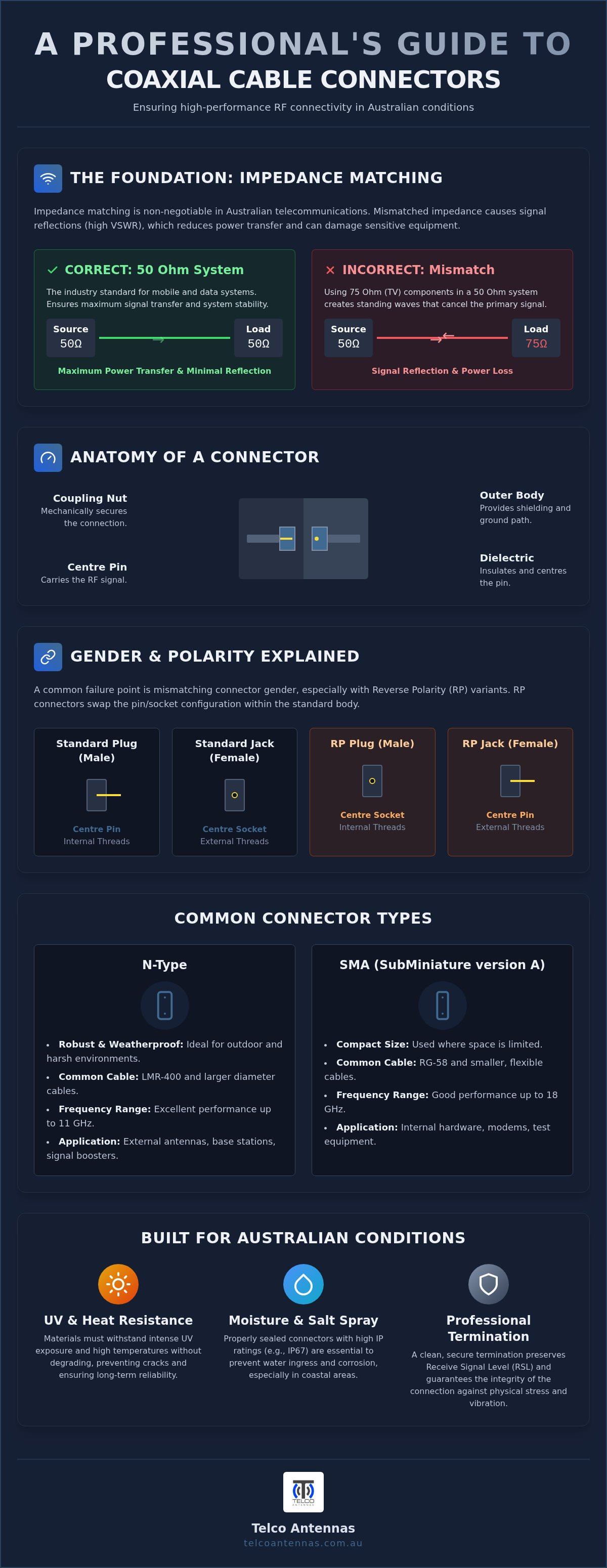
Matching impedance is a non-negotiable requirement in Australian telecommunications. Most mobile and data systems, including wireless bridges and MIMO antennas, are designed around a 50 Ohm standard. This specific value was historically chosen to balance power handling and low attenuation. Using a 75 Ohm connector, which is standard for domestic TV antennas, on a 50 Ohm mobile booster system creates a significant impedance "step". This mismatch causes signal reflections that bounce back and forth within the cable. These standing waves can cancel out your primary signal. Always verify that your hardware, from the Cel-Fi GO to the external antenna, utilises 50 Ohm components to maintain a stable Receive Signal Level (RSL).
The Anatomy and Gender of Coaxial Interfaces
Understanding the physical construction of an interface is the first step in ensuring a reliable RF link. Every component within a high-quality connector serves a specific mechanical and electrical purpose. The centre pin carries the actual signal, while the dielectric acts as a physical spacer to keep that pin perfectly centred. The outer body provides the essential ground path and shielding, and the coupling nut ensures the two halves remain joined under tension. In this coaxial cable connectors guide, we emphasise that the materials used, such as gold plating for pins and nickel for bodies, are selected specifically to resist the oxidation that often plagues remote Australian installations.
Gender in RF systems follows a strict convention. A Plug (Male) connector typically features internal threads and a protruding centre pin. Conversely, a Jack (Female) connector has external threads and a receiving socket. While this sounds straightforward, the industry often utilises "Reverse Polarity" variants which can lead to significant confusion during a site build. Whether you are using a crimp method for LMR-400 or a solder-on pin for thinner cables, choosing professional-grade RF hardware ensures that these mechanical tolerances are strictly maintained.
Standard vs Reverse Polarity (RP) Explained
Reverse Polarity (RP) connectors were originally developed to prevent users from connecting unauthorised high-gain antennas to consumer Wi-Fi equipment. The "reverse" refers specifically to the pin and socket configuration, not the threads. For example, an RP-SMA Male connector still has internal threads like a standard male, but it contains a socket instead of a pin. An RP-SMA Female has external threads but features a protruding pin. Mixing these up is a common cause of equipment damage. If you attempt to mate a standard SMA Male with an RP-SMA Female, both pins will collide, likely destroying the delicate internal sockets of your hardware.
The Importance of Precision Machining
The reliability of an RF connection depends heavily on the quality of the machining. Poorly manufactured threads can bind or cross-thread, which often results in permanent damage to expensive equipment like a Cel-Fi GO or a wireless bridge. High-performance connectors are designed to meet the IEEE Standard for Precision Coaxial Connectors, which dictates the exact physical dimensions required for consistent performance. The dielectric material must also be machined to exact specifications to ensure that the air gaps are minimised and impedance remains constant. In RF engineering, tolerance is the difference between a stable link and a "black spot" failure.
Common Coaxial Connector Types in Australian Telecommunications
Selecting the appropriate interface depends entirely on your specific hardware requirements and the environmental conditions of the installation site. While dozens of RF connectors exist globally, the Australian telecommunications landscape is dominated by a few specific standards. This coaxial cable connectors guide identifies the hardware you'll most likely encounter when deploying mobile boosters, wireless bridges, or 5G infrastructure. Each type has been engineered for a specific frequency range and power-handling capacity, making the wrong choice a primary cause of system failure.
Following professional coaxial cable termination standards is critical when working with these high-frequency interfaces. Whether you're terminating a low-loss cable in the field or selecting a pre-made assembly, understanding these four primary types is essential for a reliable link.
N-Type Connectors for Outdoor Infrastructure
The N-Type connector is the rugged workhorse of the RF industry. Its large, threaded design is specifically engineered to handle the physical weight of LMR-400 cables while providing a weather-resistant seal. This makes it the preferred choice for connecting MIMO antennas to external mounting hardware. Most N-Type connectors support frequencies up to 11 GHz, though high-precision variants can reach 18 GHz. Their robust construction allows them to withstand high-vibration environments, such as those found on mine sites or remote communication towers, without compromising the electrical connection.
SMA and Sub-Miniature Interfaces
SMA (Sub-Miniature version A) connectors are the standard for indoor telecommunications equipment. You'll find them on the antenna ports of Cel-Fi GO signal boosters and most enterprise-grade 4G/5G routers. While they are highly efficient up to 18 GHz, they are physically fragile. Over-tightening the 8mm hex nut can easily strip the threads or snap the internal dielectric. For even smaller applications, such as internal modem cards or compact IoT devices, technicians may encounter MCX or MMCX connectors. These "snap-on" interfaces are designed for tight spaces where a threaded nut is impractical, though they offer less mechanical security than a standard SMA.
Emerging Standards: 4.3-10 and Beyond
As Australia transitions toward denser 5G deployments, the 4.3-10 connector is rapidly replacing the older, bulkier 7/16 DIN standard. The primary advantage of the 4.3-10 interface is its exceptionally low Passive Intermodulation (PIM) performance. PIM occurs when two or more signals mix together in a non-linear way, creating interference that can drown out weak signals. In a professional site survey, you'll see these used in cellular base stations and distributed antenna systems (DAS) where maintaining a high signal-to-noise ratio is paramount. Additionally, while the F-Type connector is a 75 Ohm component traditionally used in satellite and digital TV, it's worth noting that it has largely replaced the older PAL (Belling-Lee) style in modern Australian residential installations due to its superior shielding and threaded security.
Selecting the Right Connector for Your Environment
Selecting a connector requires more than just checking for a physical fit. In the Australian outback, surface temperatures on equipment enclosures can exceed 50 degrees Celsius, while coastal installations face constant salt spray and high humidity. This coaxial cable connectors guide examines how these variables dictate hardware selection to prevent long-term system degradation. Environmental factors don't just affect the exterior of the connector; moisture ingress can lead to "wicking," where water travels up the cable's braid and destroys the dielectric properties of the entire run.
Ingress Protection (IP) ratings are the primary metric for evaluating a connector's suitability for outdoor use. For most Australian RF installations, an IP66 or IP67 rating is the professional benchmark. These ratings ensure the interface is dust-tight and can withstand powerful water jets or temporary immersion. As frequencies move from the MHz range into the higher GHz bands used by 5G, the physical size of the connector also impacts signal attenuation. Larger connectors, such as the N-Type, generally offer lower insertion loss because they accommodate the thicker centre conductors found in low-loss cables like LMR-400.
Weatherproofing Remote Australian Installations
Standard PVC electrical tape is insufficient for protecting outdoor joins. It becomes brittle under intense UV exposure and eventually peels, allowing moisture to enter the threads. Technicians should always use self-amalgamating tape, which chemically fuses into a seamless, waterproof mass when stretched and wrapped. Another essential technique is the "drip loop." By creating a small U-shaped bend in the cable before it enters a building or enclosure, you ensure that gravity pulls rainwater away from the connection point. For coastal environments, avoid cheap plated alloys; high-grade brass or stainless steel components are required to resist galvanic corrosion over time.
Cable Compatibility: Matching Connectors to Coax
A common error in the field is attempting to use a connector designed for one cable type on another. For instance, an SMA connector designed for RG-58 has a different internal crimp diameter than one engineered for LMR-400. Forcing a fit will inevitably crush the dielectric or result in a loose centre pin, both of which cause massive impedance spikes. If you must bridge different connector types, use a short, factory-terminated "pigtail" rather than a series of hard adapters. Every adapter in a signal path introduces a "loss tax" of approximately 0.1dB to 0.5dB. To maintain your Receive Signal Level (RSL), you can find a range of high-performance RF components specifically matched to Australian cable standards.
Ensuring Professional-Grade Terminations with Telco Antennas
Applying the technical principles found in this coaxial cable connectors guide is the final step in securing a high-performance RF link. While understanding impedance and gender is essential, the physical execution of the termination determines whether your system achieves its theoretical maximum Receive Signal Level (RSL). In the demanding Australian climate, a minor oversight during assembly often leads to moisture ingress or mechanical failure within months. Telco Antennas bridges this gap by providing hardware and engineering expertise that translates complex RF theory into functional, long-term installations.
Why Factory Terminations Beat Field Crimping
Field-terminated cables are a frequent source of "intermittent" signal issues. Standard hand-crimping tools often apply uneven pressure, which can slightly deform the cable's dielectric and create impedance spikes. In contrast, factory-terminated LMR-400 coaxial cables utilise precision hydraulic crimping systems that ensure 360-degree uniform compression. This creates a gas-tight seal between the connector body and the cable braid, preventing the oxidation that degrades signal over time. Every assembly is finished with adhesive-lined heat-shrink tubing to provide a secondary layer of environmental protection. Most importantly, factory-built cables undergo Voltage Standing Wave Ratio (VSWR) testing before they reach the site, ensuring that the "loss tax" of the join is kept to an absolute minimum.
Beyond standard cellular setups, specialised connectivity requirements often demand custom solutions. If you are integrating a Starlink system into a remote or industrial environment, Telco Antennas supports aftermarket power conversions that allow for more robust hardware integration. These conversions enable users to move away from proprietary, fragile connectors toward standardised RF interfaces that are better suited for permanent outdoor mounting on communication towers or telescopic masts.
Consultative Support for Australian Connectivity
For large-scale industrial projects or complex site builds, selecting the right connector is only one part of the equation. Professional RF site surveys are often necessary to identify the optimal placement for MIMO antennas and to calculate the precise link budget for long-distance transmissions. If your project requires communication tower design or the deployment of high-capacity wireless bridges, a consultative approach ensures that every component, from the aluminium tri-pod to the LMR-400 jumper, is matched for maximum throughput. Our expert team provides bespoke cabling services, allowing you to specify exact lengths and connector combinations that eliminate the need for signal-draining adapters in your RF path.
Optimising Your RF Network for Long-Term Performance
Mastering the technical requirements of your transmission line is the most effective way to eliminate signal dropouts and ensure your hardware operates at its peak capacity. This coaxial cable connectors guide has detailed why matching 50 Ohm impedance and selecting the correct mechanical interface, such as the rugged N-Type or the compact SMA, are critical steps for any Australian installation. Whether you are deploying a Cel-Fi GO in a remote black spot or integrating a high-throughput MIMO antenna system, the focus must always remain on minimising insertion loss through precision machining and robust weatherproofing.
Since 2008, Telco Antennas has operated as an Australian-owned specialist in remote and industrial RF engineering. We maintain a comprehensive stock of genuine LMR-400 low-loss cable and high-performance interfaces designed to withstand the harshest environmental variables. If you are ready to move from theory to a functional, high-performance setup, you can browse our range of high-performance coaxial cables and connectors today. Implementing these professional standards will give you the confidence that your connectivity remains stable regardless of the situational challenges you face.
Frequently Asked Questions
What is the most common connector for Australian mobile antennas?
The N-Type (Male) connector is the most prevalent interface for external mobile antennas across Australia. It's preferred for its rugged, weather-resistant design and its ability to accommodate low-loss cables like LMR-400. While the antenna end usually features an N-Type interface, the indoor equipment end, such as a Cel-Fi GO, typically utilises a smaller SMA connector. Always verify the gender and polarity before purchasing your cable assemblies to avoid installation delays.
Can I use a TV antenna connector for my 4G signal booster?
You cannot use standard TV antenna connectors for a 4G signal booster because they operate on a 75 Ohm impedance standard. Mobile boosters and cellular antennas require 50 Ohm components to function correctly. Mixing these standards creates a significant impedance mismatch, which leads to signal reflections and high VSWR. This mismatch can cause your booster to reduce its power output or potentially suffer hardware damage due to reflected heat.
What is the difference between SMA and RP-SMA connectors?
The difference lies in the configuration of the centre pin and socket rather than the threads. A standard SMA Male has a centre pin, while a Reverse Polarity (RP-SMA) Male features a centre socket. This variation was introduced to prevent the connection of high-gain antennas to consumer Wi-Fi equipment. Because they are mechanically incompatible, attempting to join a standard SMA to an RP-SMA interface will likely destroy the delicate internal pins and sockets.
How do I stop water from getting into my outdoor coax connections?
Preventing water ingress requires a combination of mechanical barriers and proper cable routing. You should wrap all outdoor joins with self-amalgamating tape, which fuses into a waterproof seal, rather than relying on standard electrical tape. Additionally, always incorporate a drip loop before the cable enters a building or enclosure. This simple U-shaped bend ensures that gravity pulls rainwater away from the connector interface, protecting the dielectric from moisture wicking and long-term corrosion.
Why does the length of my coaxial cable matter for connector choice?
Cable length dictates the thickness of the cable required to manage signal attenuation, which in turn determines the connector type. For long runs, you'll need low-loss LMR-400 cable, which is too thick for small SMA connectors and requires larger N-Type interfaces. This coaxial cable connectors guide recommends matching your connector to the cable's physical diameter to ensure a secure crimp and to maintain the integrity of the 50 Ohm signal path.
Do I need special tools to install an N-Type connector on LMR-400?
Yes, installing an N-Type connector on LMR-400 requires a dedicated ratcheting crimp tool with the correct die size for the outer sleeve. You'll also need a coaxial cable stripper set to the specific depths for the centre conductor and dielectric. While field crimping is possible, factory-terminated cables are generally superior because they use hydraulic crimpers and undergo VSWR testing. If you are doing it yourself, ensure you have a heat gun for the adhesive-lined heat-shrink.
What is a pigtail adapter and when should I use one?
A pigtail is a short length of flexible coaxial cable used to bridge two different connector types or to reduce mechanical strain on a port. You should use one when connecting a thick, rigid cable like LMR-400 to a fragile device port, such as the SMA input on a router. This prevents the weight of the heavy cable from snapping the internal solder joins of your hardware while providing the necessary interface conversion.
How can I tell if my coaxial connector is damaged or failing?
Visual indicators of failure include green or white oxidation on the metal surfaces, bent centre pins, or a loose coupling nut. Electrically, a failing connector often manifests as a sudden drop in your Receive Signal Level (RSL) or a significant increase in data latency. If you notice the signal fluctuates when you physically move the cable, the internal crimp or solder join has likely failed. In these cases, the entire connector should be replaced immediately.


