
Investing in a high-gain antenna only to pair it with standard RG-58 is like trying to run a high-pressure fire hose through a garden straw. In the vast Australian landscape, where remote sites often struggle with signal drop-out, every decibel of gain is hard-won. Many professional installations fail because the transmission line throttles hardware performance. Using lmr-400 coaxial cables provides the 50-ohm impedance and high velocity of propagation required to maintain signal integrity over longer runs. This cable is the critical engineering bridge that prevents high-performance equipment from being undermined by avoidable attenuation.
You likely recognise the frustration of signal degradation caused by harsh UV exposure or interference. This guide provides the technical clarity needed to master lmr-400 coaxial cables, from calculating precise decibel loss to selecting correct connectors. We will examine the physical properties of this industry-standard 10.29mm diameter cable and explain why its foil and braid shielding is essential for zero-fail connectivity. By the end of this briefing, you will understand how to organise your RF infrastructure to ensure maximum throughput in challenging Australian environments.
Key Takeaways
- Understand why LMR-400 is the industry benchmark for low-loss transmission in high-interference Australian environments.
- Learn to calculate exact signal attenuation for lmr-400 coaxial cables across critical 5G and mobile frequencies.
- Identify when to upgrade from standard RG-series cables to prevent signal bottlenecking in long cable runs.
- Gain professional insights into connector compatibility and the mechanical requirements for successful cable termination.
- Discover how to integrate high-performance cabling with Starlink systems and Cel-Fi GO boosters for reliable remote connectivity.
LMR-400 Coaxial Cable: Why is it the Industry Standard?
LMR-400 has established itself as the de facto choice for RF professionals across Australia. While older coaxial cable standards like the RG-series served basic radio needs for decades, they often fall short in modern high-frequency environments. LMR-400 coaxial cables are specifically engineered to provide a 50-ohm, low-loss transmission line that balances physical durability with electrical efficiency. This performance is vital in Australian signal black spots, where every decibel preserved between the antenna and the receiver determines whether a site remains connected or drops offline. Its primary applications include cellular boosters, commercial WiFi extensions, and radio base stations where signal integrity is paramount.
The Anatomy of Professional Grade Coax
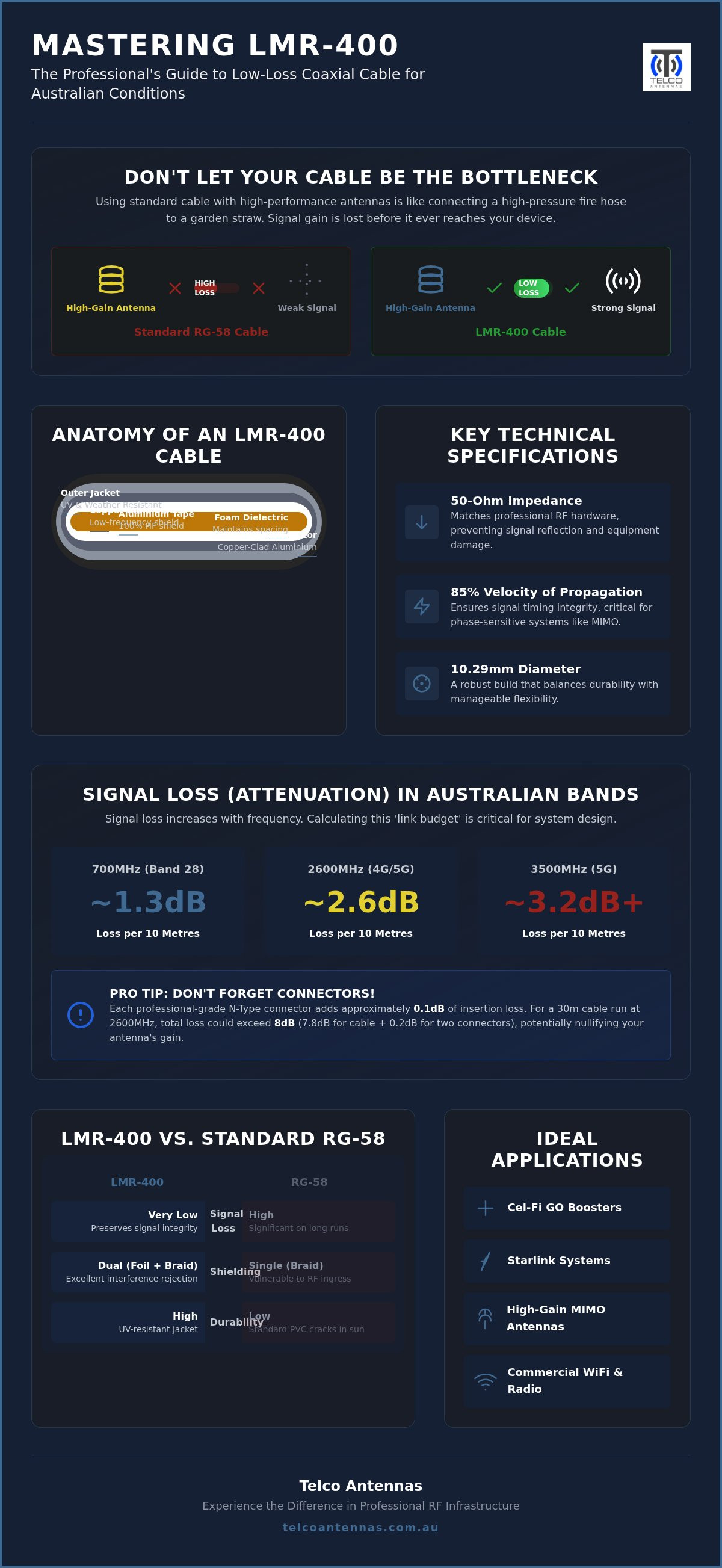
The reliability of this cable stems from its mechanical composition. At its centre lies a solid copper-clad aluminium conductor. This design utilises the "skin effect" where high-frequency signals travel primarily along the outer surface of the conductor, allowing for the conductivity of copper without the weight or cost of a solid copper core. Surrounding this is a closed-cell foam polyethylene dielectric. This layer is critical because it maintains the physical spacing between the conductor and the shield, ensuring a high velocity of propagation. To eliminate interference, lmr-400 coaxial cables employ a dual-shielding system. An outer layer of tinned copper braid provides structural strength and low-frequency protection, while an inner layer of aluminium tape offers 100% coverage to block high-frequency ingress.
Why 50-Ohm Impedance Matters for Australian RF
In the context of Australian telecommunications, impedance matching is a non-negotiable requirement for system stability. Most professional hardware, including Cel-Fi GO Mobile Signal Boosters and high-gain MIMO antennas, is designed for a 50-ohm environment. If you introduce a cable with a different impedance or poor manufacturing tolerances, you create a mismatch. This results in signal reflections where energy travels back toward the source rather than out through the antenna. Such reflections lead to Voltage Standing Wave Ratio (VSWR) issues, which can overheat sensitive equipment or cause the system to throttle its output to protect its internal circuitry. VSWR is the ratio of reflected to transmitted power. By using high-quality LMR-400, you ensure that the maximum amount of RF energy reaches its destination without damaging the hardware or degrading the signal-to-noise ratio.
Technical Specifications: Understanding Attenuation and Power Handling
Mastering the electrical limits of lmr-400 coaxial cables is essential for any professional RF deployment. According to the LMR-400 official specifications, this cable features a velocity of propagation of approximately 85%. This high velocity is vital for phase-sensitive systems such as MIMO antenna arrays, where timing synchronisation between multiple signal paths must be maintained. If the velocity is inconsistent, the digital signal processing at the receiver may struggle to reconstruct the data stream, leading to reduced throughput. Power handling is another mechanical strength. In industrial base station environments, these cables can safely manage significant wattage, though capacity decreases as frequency rises. For most Australian cellular and WiFi applications, the thermal limits are rarely reached, yet the headroom provides a necessary safety margin for high-output transmitters.
Frequency-Specific Loss in Australian Mobile Bands
Attenuation is the primary enemy of signal strength. In the Australian context, we often deal with the 700MHz band (B28) for regional coverage. At this frequency, lmr-400 coaxial cables lose roughly 1.3 dB per 10 metres. However, if you move to the 2600MHz band or 3.5GHz 5G bands, that loss increases significantly. At 2600MHz, loss sits near 2.6 dB per 10 metres. Calculating a link budget requires adding these losses to your connector insertion loss, which is typically 0.1 dB per professional-grade N-Type connector. If your cable run is 30 metres at high frequency, you could lose over 8 dB, which might nullify the gain of your antenna entirely. You can consult our technical team to help calculate these losses for your specific site requirements.
Environmental Durability in the Australian Sun
Australian conditions are notoriously punishing on external hardware. Standard PVC-jacketed cables often crack within two years due to intense UV exposure. LMR-400 utilises a UV-protected black Polyethylene (PE) jacket designed to withstand decades of direct sunlight without structural degradation. It maintains its electrical properties across a wide operating temperature range, typically from -40°C to +85°C. This ensures consistent performance during a 45°C summer day in the outback. To prevent moisture ingress, which can rapidly increase attenuation by saturating the dielectric foam, always use sealed connectors and weatherproofing tape during the final installation phase. Proper sealing ensures the cable's internal impedance remains stable regardless of humidity or rain.
LMR-400 vs. Alternatives: When to Upgrade Your Cabling
Selecting the correct transmission line is a technical balancing act between physical constraints and electrical performance. While many budget-conscious installers gravitate toward RG-58 or RG-213 due to legacy familiarity, these choices often lead to systemic failure in modern high-frequency applications. According to the ARRL coaxial cable guide, the physical dimensions and dielectric materials of a cable dictate its attenuation profile. If your installation involves a run longer than 10 metres or operates in high-frequency 4G or 5G bands, staying with older standards will likely bottleneck your equipment. When a site survey reveals extreme distances, such as tower runs exceeding 50 metres, it is time to consider stepping up to LMR-600 to keep the link budget viable.
LMR-400 vs. RG-58: The Signal Killer
The performance gap between standard RG-58 and lmr-400 coaxial cables is stark when quantified across a typical installation. On a 15-metre run at 1800MHz, RG-58 can lose upwards of 10dB, whereas LMR-400 loses roughly 3dB. Every 3dB of loss represents a 50% reduction in signal power. This means that by choosing a cheaper, thinner cable, you are effectively throwing away half of your transmitted energy before it even reaches the antenna. This level of inefficiency completely negates the performance benefits of a high-gain MIMO antenna, making the entire system investment counterproductive. For shorter jumper leads or internal cabinet wiring where space is at a premium, LMR-240 offers a more manageable diameter while still outperforming RG-58.
UltraFlex: Solving the Rigidity Challenge
Standard LMR-400 features a solid centre conductor, which provides the lowest possible loss but limits flexibility. In scenarios where cables must pass through tight vehicle bulkheads or operate on moving parts like telescopic masts, UltraFlex is the pragmatic alternative. UltraFlex utilises a stranded copper centre conductor and a rubberised outer jacket to improve the bending radius. While this makes routing significantly easier, it does come with a slight increase in attenuation compared to the solid-core version. If your project involves a fixed, static installation, stick with standard lmr-400 coaxial cables for maximum efficiency. If the cable must flex frequently or follow a complex path through a vehicle interior, the mechanical longevity of UltraFlex outweighs the minor decibel trade-off.
Professional Installation: Connectors, Bending, and Routing
A professional installation ensures that the theoretical performance of lmr-400 coaxial cables translates into real-world reliability. Termination requires a level of precision that cannot be achieved with basic hand tools; you must use a dedicated LMR-400 stripping tool and a calibrated hex crimper. Poorly stripped jackets or crushed dielectrics create impedance bumps that lead to signal reflections. If the internal foam dielectric is compressed during the crimping process, it permanently alters the cable's 50-ohm characteristic impedance. Physical handling is equally critical. With an outer diameter of approximately 10.29mm, these cables have a minimum bend radius of 25.4mm for a single bend. Exceeding this limit causes the centre conductor to migrate through the foam, which increases signal attenuation and compromises the system's Voltage Standing Wave Ratio (VSWR).
Connector Compatibility and Adaptors
Choosing the correct interface is vital for long-term system stability. N-Male connectors are the industry standard for High-Performance MIMO Antennas because they provide a robust, threaded connection with superior weather resistance. While many desktop cellular boosters utilise smaller SMA ports, you should avoid using multiple adaptors to bridge the gap. Each junction introduces roughly 0.1 dB of insertion loss and creates a potential point of failure. It is more efficient to use a cable pre-terminated with the correct N-to-SMA configuration. In humid or coastal Australian environments, ensure your connectors feature gold-plated centre pins. This prevents the oxidation that can occur with cheaper nickel-plated alternatives, maintaining a low-resistance electrical path for the life of the installation.
Routing Cable for Maximum Performance
Strategic routing protects your signal from external interference and environmental degradation. You should never run lmr-400 coaxial cables parallel to AC mains power lines, as the electromagnetic field from the 240V supply can induce noise into your RF line. Aim for at least 300mm of separation where possible. When securing the cable to a mast or building, use UV-rated cable ties or flexible conduit to prevent the jacket from cracking under the intense Australian sun. One essential step for any outdoor run is the inclusion of a drip loop. By allowing the cable to dip below the entry point of a building or enclosure, you ensure that rainwater runs off the bottom of the loop rather than following the cable jacket into your sensitive hardware. For a guaranteed professional result, you can purchase custom-terminated cable assemblies tailored to your exact site dimensions.
LMR-400 Solutions for Starlink and Remote Signal Boosting
Modern connectivity in regional Australia often relies on a combination of satellite backhaul and local cellular enhancement. While lmr-400 coaxial cables are traditionally associated with radio and mobile networks, they play a vital role in high-performance satellite ecosystems when paired with Starlink Aftermarket Power Solutions. In these setups, the goal is often to extend high-speed data from a primary terminal to a secondary location or to ensure that a mobile signal booster has the cleanest possible donor signal. Deploying a Cel-Fi GO booster without high-quality cabling essentially wastes the gain provided by the amplifier. By using LMR-400, you maintain the signal-to-noise ratio required for the booster to operate at its maximum 100dB gain, ensuring reliable voice and data coverage in areas where signal is otherwise non-existent.
Starlink and LMR-400 Integration
While Starlink terminals utilise proprietary or Ethernet cabling for their primary dish-to-router connection, lmr-400 coaxial cables are essential for the secondary RF infrastructure. If you are extending the reach of a Starlink Mini in an off-grid setup, you might utilise a point-to-point wireless bridge to beam the connection to a distant shed or homestead. These bridges require low-loss transmission lines to connect the radios to high-gain sector antennas. Using 400-series cable ensures that the power conversion efficiency of your system remains high, as you aren't forcing the radios to compensate for massive cable losses. This is particularly important for 12V or 24V DC-powered sites where every watt of power consumption must be accounted for. Reducing transmission loss means the radios can operate at lower power levels while maintaining the same link stability.
The Telco Antennas Engineering Advantage
Off-the-shelf cable assemblies often use inferior components or lack the precise termination required for industrial-grade telecommunications. A single poorly fitted connector can introduce enough passive intermodulation (PIM) to degrade a high-speed data link. For complex sites with high interference or difficult terrain, we recommend requesting a Professional RF Site Survey. This process allows our engineers to determine the optimal placement for antennas and calculate the exact cable lengths required to stay within your link budget. Once the design is finalised, you can optimise your signal today with Telco Antennas Custom LMR-400 Assemblies. Our custom services ensure that every cable is terminated with professional-grade connectors and tested for electrical integrity before it arrives at your site, removing the guesswork from your installation.
Optimising Your RF Infrastructure for Long-Term Reliability
Maintaining high-speed connectivity in regional Australia requires more than just high-gain antennas; it demands a transmission line that preserves every decibel of signal strength. By understanding the specific attenuation profiles and mechanical requirements of lmr-400 coaxial cables, you can eliminate the bottlenecks that often plague remote installations. Whether you're extending a Starlink terminal or deploying a Cel-Fi GO booster, the technical integrity of your connectors and the precision of your cable routing are the final steps in securing zero-fail connectivity.
Telco Antennas has been Australian-owned and operated since 2008, providing the professional RF engineering support necessary to navigate complex telecommunications challenges. Our team provides custom cable lengths terminated to order, ensuring your hardware is supported by professional-grade components from the start. Browse our range of High-Performance LMR-400 Cables and Assemblies to ensure your next deployment meets the highest engineering standards. With the right infrastructure in place, you can move forward with the confidence that your communication links will remain stable in even the most punishing environments.
Frequently Asked Questions
How far can I run LMR-400 cable before I lose too much signal?
The maximum distance depends on your operating frequency and the gain of your antenna. For lower frequency bands like 700MHz, you can run lmr-400 coaxial cables up to 30 metres while maintaining a viable link budget. However, at higher 5G frequencies like 3.5GHz, attenuation increases significantly. We generally recommend keeping runs under 15 metres in these scenarios to ensure the cable loss doesn't completely negate the gain provided by your antenna system.
Is LMR-400 waterproof for outdoor use in Australia?
Standard LMR-400 is designed with a UV-protected Polyethylene (PE) jacket that is fully waterproof and capable of withstanding the intense Australian sun. While the cable itself is impervious to moisture, the connectors are the most common point of failure. You must use professional-grade weatherproofing tape or heat-shrink tubing at every outdoor junction. This prevents water from wicking into the foam dielectric, which would otherwise lead to rapid signal degradation and cable failure.
Can I use LMR-400 for my Starlink installation?
You cannot use LMR-400 as a direct replacement for the proprietary Starlink dish cable, as Starlink Gen 2 and Gen 3 systems utilise Power over Ethernet (PoE) or RJ45 connectors rather than coaxial RF lines. However, lmr-400 coaxial cables are the ideal choice for extending your network via point-to-point wireless bridges. If you need to beam your Starlink connection to a remote shed, LMR-400 provides the low-loss path required for high-frequency bridge antennas.
What is the difference between LMR-400 and LMR-400 UltraFlex?
The primary difference lies in the centre conductor and the outer jacket material. Standard LMR-400 uses a solid copper-clad aluminium core for the lowest possible signal loss in static installations. UltraFlex utilises a stranded copper core and a thermoplastic rubber jacket, making it much more flexible for vehicle installs or moving masts. While UltraFlex is easier to route through tight spaces, it has slightly higher attenuation than the standard version over the same distance.
Do I need special tools to install connectors on LMR-400?
Professional termination requires a dedicated LMR-400 cable stripper and a heavy-duty hex crimping tool. Using a standard utility knife often nicks the centre conductor or deforms the foam dielectric, which creates impedance mismatches. A calibrated crimper ensures the connector sleeve is compressed evenly around the braid without crushing the cable's internal structure. If you don't have access to these tools, we recommend purchasing custom-terminated assemblies to guarantee electrical performance and physical durability.
Is LMR-400 compatible with Telstra and Optus 5G frequencies?
Yes, LMR-400 is fully compatible with all current Australian mobile bands, including the 700MHz (B28) long-range band and the 3.5GHz 5G NR bands used by Telstra and Optus. It is rated for use up to 6GHz, making it a future-proof choice for evolving telecommunications standards. Since 5G signals are more susceptible to attenuation, using a high-quality, low-loss cable is even more critical than it was for older 3G or 4G LTE deployments.
Why is LMR-400 so much thicker than standard TV antenna cable?
Standard TV cable is usually RG-6, which is a 75-ohm cable designed for receive-only video signals. LMR-400 is a 50-ohm cable engineered for two-way RF transmission. The increased thickness, roughly 10.29mm, is necessary to accommodate a larger centre conductor and a thick foam dielectric. This physical size is what allows the cable to achieve significantly lower attenuation levels, which is vital for maintaining the signal integrity of mobile boosters and wireless bridges.
Can LMR-400 be buried underground?
Standard LMR-400 with a PE jacket can be buried if it is placed inside a protective PVC conduit to prevent mechanical damage. However, for direct burial without conduit, you should use the LMR-400-DB variant. This version contains a specific waterproofing compound under the jacket that acts as a sealant if the outer layer is ever nicked. This prevents moisture from travelling along the cable, protecting your hardware from water ingress over the long term.


