
Did you know that using a standard AC inverter to power your Starlink dish can waste up to 15 per cent of your battery capacity through unnecessary heat and conversion loss? For those of us operating in remote areas, every watt-hour is a precious resource that dictates how long we can stay off-grid. You've likely felt the frustration of watching your battery levels plummet just to keep a bulky, domestic router running while worrying that a cheap, uncertified Starlink aftermarket power conversion might damage your expensive hardware. It's a common challenge for anyone trying to maintain a reliable connection in a vehicle or a remote hut where mobile coverage is non-existent.
This technical guide will show you how to master your power setup to achieve superior efficiency and reliability. We'll examine the precise voltage requirements for 2026 hardware versions, including the specific 24V and 54V needs of the Mini and Standard Gen 4 dishes. By the end of this article, you'll understand how to bypass standard routers and integrate high-performance step-up converters into a compact, robust system. We'll also discuss how these setups interact with external hardware like MIMO antennas and LMR-400 cabling to ensure your remote telecommunications are both streamlined and professional.
Key Takeaways
- Learn why bypassing standard 240V AC inverters can reclaim up to 20 per cent of your battery capacity by eliminating heat and conversion losses.
- Understand the specific voltage requirements for different hardware generations, ensuring your starlink aftermarket power conversion provides the stable 48V to 57V required for reliable operation.
- Discover how to manage voltage drop in remote installations by selecting the correct cable gauge to maintain signal integrity over long DC runs.
- Follow a logical selection process to identify your hardware's native power needs and calculate a precise daily Watt-hour budget for your battery bank.
- Explore how to integrate your Starlink setup with professional-grade components like MIMO antennas to create a robust, mission-critical communication system.
Understanding Starlink Aftermarket Power Conversion for Off-Grid Use
A starlink aftermarket power conversion is the process of bypassing the standard 240V AC power supply provided by SpaceX and replacing it with a direct DC-to-DC system. This modification allows the hardware to draw power directly from a 12V or 24V battery bank, which is the standard configuration for most Australian caravans, 4WDs, and remote telecommunications huts. The Starlink satellite internet constellation requires a consistent and high-current power source to maintain the phased-array antenna's connection; however, the domestic hardware is not natively designed for the realities of off-grid energy management.
By 2026, professional-grade deployments in remote areas have shifted toward native DC integration to solve three primary issues: excessive thermal output, hardware footprint, and energy efficiency. When you eliminate the need for an AC inverter, you create a more reliable system that generates less heat in confined spaces and extends your battery runtime significantly. This approach is essential for mission-critical sites where maintaining a connection in "black spots" is non-negotiable.
The Inefficiency of the Standard Starlink AC Setup
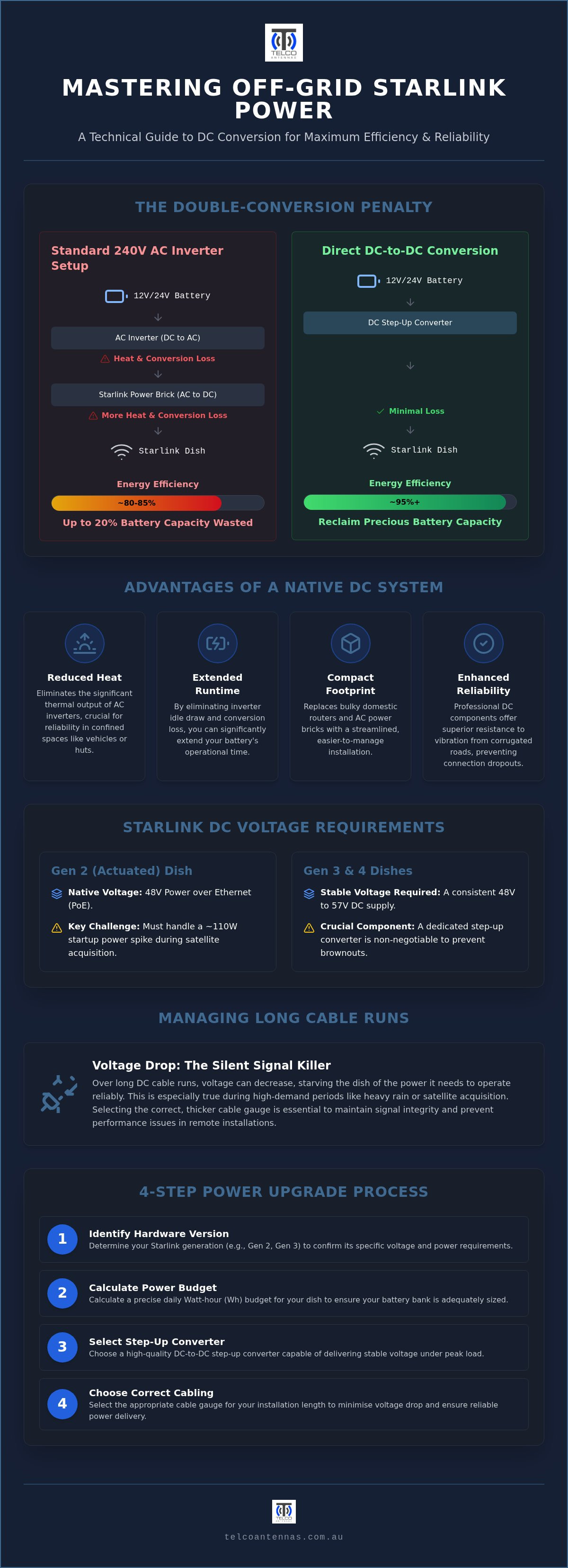
The standard out-of-the-box configuration forces a double-conversion penalty that is highly detrimental to small-scale solar systems. Your battery stores power as Direct Current (DC). A standard inverter must convert this to 240V Alternating Current (AC), only for the Starlink power brick to convert it back to a high-voltage DC signal for the dish. Each stage of this process loses energy as heat.
Research indicates that direct DC conversion is approximately 15 per cent more efficient than using an AC inverter. The "idle power draw" of a standard inverter is a silent killer of battery banks; even when the dish is consuming its average 31W during normal operation, the inverter itself may be drawing additional current just to stay active. For a remote user, this inefficiency can mean the difference between a system that runs through the night and one that triggers a low-voltage disconnect before sunrise.
The Mechanical Advantage of Native DC Power
Beyond electrical efficiency, a starlink aftermarket power conversion offers significant mechanical benefits for mobile users. Standard domestic routers and proprietary AC bricks are bulky and difficult to secure. By moving to a DC-to-DC setup, you can remove the factory router entirely and utilise more robust, compact networking hardware that integrates directly into your existing 12V or 24V distribution board.
Australian corrugated roads present a unique challenge for domestic-grade electronics. Standard AC plugs and domestic-style power bricks are prone to working loose or suffering internal board fatigue under constant high-frequency vibration. Professional DC conversion components are typically built to higher engineering standards, offering better vibration resistance and simplified cable management. This creates a streamlined installation that is easier to troubleshoot and far more likely to survive the rigours of long-distance travel in harsh environments.
Technical Specifications: DC-to-DC Requirements for Gen 2 vs Gen 3
Selecting the correct components for a starlink aftermarket power conversion depends entirely on which generation of hardware you're deploying. While your battery bank likely sits at 12V or 24V, the dish itself operates at much higher voltages to push power through Ethernet runs without excessive loss. A simple 12V bypass isn't sufficient because the terminal requires a stable, high-voltage DC supply to maintain the signal during high-demand periods like satellite acquisition or heavy rain fade. Without a dedicated step-up converter, your system will likely suffer from brownouts or constant reboots under load.
Gen 2 (Actuated) Electrical Parameters
The Gen 2 Actuated dish relies on a 48V Power over Ethernet (PoE) configuration. This setup mirrors the logic behind the IEEE 802.3bt standard, which allows for high-wattage delivery over twisted-pair data cables. When modifying the proprietary Gen 2 cable, you face a significant risk of pin-out errors that can lead to permanent hardware failure. It's vital to use a converter that can handle the 110W startup spike while averaging roughly 31W during steady-state operation. Most technicians prefer a 12V to 48V step-up module with a high amperage ceiling to account for these initial surges.
Gen 3 (Standard/V4) and the 57V Standard
The Gen 3 Standard terminal has moved the goalposts by requiring a 57V input for optimal performance. This higher voltage ensures the phased-array antenna remains stable during peak data throughput and prevents signal degradation. Unlike previous models, the Gen 3 utilises a standard RJ45 connector, which simplifies the physical installation but places more stress on the DC-DC converter's thermal management. Because these converters generate heat while stepping up 12V to 57V, they must be mounted in ventilated areas or on heat-sinking surfaces to prevent thermal throttling during hot Australian summers.
The Starlink Mini has introduced a more flexible approach, accepting 12V to 20V DC inputs natively. However, even with the Mini, professional installers often prefer a 24V step-up to ensure voltage stability over longer cable runs. If you're planning a complex installation, it's worth reviewing high-performance Starlink power conversion kits that are engineered to handle these specific electrical loads. Proper planning for amperage spikes is critical; failing to account for the 100W+ draw during startup or rain fade can cause your system to reboot at the exact moment you need the connection most. This reliability is especially important when integrating with other hardware like MIMO antennas where consistent power is the foundation of the entire signal chain.
Managing Voltage Drop and Signal Integrity in Remote Installations
Maintaining a high-speed connection in the Australian outback requires more than just the right dish; it demands a physical installation that respects the laws of electrical physics. As many operators transition to off-grid renewable energy solutions, the challenge of managing voltage drop becomes a primary engineering hurdle. In a starlink aftermarket power conversion, the distance between your battery bank and the DC-DC converter is the most critical variable in determining whether your system will remain stable under load.
Calculating Voltage Drop for 12V Starlink Systems
A 12V system is particularly vulnerable to voltage drop because it requires significantly higher amperage to deliver the same wattage as a 24V or 48V system. For example, a 100W startup surge draws approximately 8.3 Amps at 12V. If you use thin, undersized cabling over a three-metre run, the resistance within the wire will cause the voltage to sag. This often results in the terminal rebooting or failing to acquire a satellite lock. To mitigate this, you should always place the DC-DC converter as close to the battery bank as possible and utilise heavy-gauge, high-strand copper wiring. For a 57V Starlink system, the maximum acceptable voltage drop should not exceed 3 per cent to ensure the terminal remains operational during peak power events.
RF Cleanliness and Shielding
Another frequently overlooked factor is RF cleanliness. Poorly engineered converters often produce high levels of electromagnetic interference (EMI) due to low-quality switching components. This "switching noise" can bleed into the surrounding environment, potentially degrading the performance of your MIMO antennas and reducing overall data throughput. In professional 2026 deployments, technicians prioritise converters with integrated shielding and high-frequency filtering to protect the integrity of the local RF environment. This is especially vital when the system is installed near sensitive cellular boosters or other radio equipment.
Protecting the phased-array antenna also requires a robust electrical defence strategy. A professional starlink aftermarket power conversion must include over-voltage, under-voltage, and short-circuit protection to prevent a component failure from destroying the expensive dish hardware. Utilising shielded RJ45 connectors and high-quality Starlink accessories Australia ensures that the entire signal chain is grounded and isolated from external interference, providing a level of reliability that generic consumer-grade hardware simply cannot match.
Step-by-Step Selection Guide for Starlink Power Upgrades
Selecting a starlink aftermarket power conversion requires a methodical approach to ensure electrical compatibility and long-term hardware survival. A haphazard installation often leads to intermittent connectivity or, worse, permanent terminal damage. To achieve a professional-grade result, you should follow a structured sequence that prioritises engineering standards over convenience.
- Step 1: Identify Hardware Generation. Confirm whether you are deploying a Gen 2 Actuated (48V), a Gen 3 Standard (57V), or a Starlink Mini. Each hardware version requires a specific step-up profile to maintain signal stability.
- Step 2: Calculate Daily Energy Budget. While the terminal averages 31W, you must calculate your total daily Watt-hour (Wh) requirements. This calculation helps determine if your current battery bank and solar array can sustain the ~744Wh daily draw alongside other essential appliances.
- Step 3: Choose Your Integration Level. Decide between a modular DIY setup or a pre-assembled kit. This decision impacts both your installation time and the overall resilience of the system.
- Step 4: Audit Network Hardware. Determine if you will retain the Starlink router or bypass it for an industrial 12V alternative to further reduce power consumption.
- Step 5: Verify Thermal and Amperage Ratings. Ensure your starlink aftermarket power conversion hardware can handle 2026 environmental variables and the 110W startup spikes common during satellite acquisition.
Modular DIY vs. Integrated Kits
A modular DIY approach involves sourcing individual PoE injectors and step-up modules. While this can be cost-effective for hobbyists, it introduces multiple points of failure and increases the risk of pin-out errors during assembly. Conversely, integrated kits provide a fused, pre-assembled solution that has been rigorously tested for voltage stability. For mission-critical deployments or long-term remote use, the reliability of a professional kit far outweighs the minor savings of a DIY build. If you require a dependable off-grid setup, it is advisable to browse the range of high-performance Starlink power conversion kits designed specifically for the harsh Australian environment.
Integrating Third-Party Routers
The standard Starlink router is a significant contributor to total power consumption. Bypassing it allows you to use 12V-native industrial routers, which offer superior network management and lower idle draw. When selecting a third-party router, you must ensure it is compatible with your PoE injector's power delivery profile. This streamlined approach not only reduces your energy footprint but also allows for better integration with cellular redundancy systems. This ensures your remote site remains connected even during satellite outages or heavy rain fade events.
Professional RF Integration: The Telco Antennas Approach
Achieving a reliable connection in Australia's most challenging environments requires an approach that transcends simple hardware assembly. While a basic starlink aftermarket power conversion solves the immediate energy efficiency problem, professional-grade installations must account for the intersection of power stability and signal integrity. We prioritise engineering standards that ensure every component, from the DC-DC converter to the cabling, can withstand the thermal and mechanical stresses of the outback. This methodical strategy is essential for industrial, agricultural, and emergency service fleets where a loss of connection is not merely an inconvenience but a critical failure.
Beyond the Dish: A Holistic Connectivity Strategy
In many professional 2026 deployments, Starlink serves as a robust backhaul for broader network architectures. By utilising point-to-point wireless bridges, you can distribute high-speed internet from a centrally powered Starlink terminal to multiple remote outbuildings or sensor arrays. For permanent installations, the integrity of the communication tower design is paramount. We validate all hardware for the harsh Australian climate, ensuring that mounting structures and cabling enclosures can handle high-UV exposure and extreme temperature fluctuations. When temporary or rapid deployments are required, telescopic mast trailers provide a mobile platform that combines a stable RF profile with integrated power management.
Securing Your Remote Infrastructure
A starlink aftermarket power conversion is only as good as the enclosure that protects it. Physical security and weatherproofing are non-negotiable for DC conversion hardware installed in exposed locations. We recommend using IP-rated cabinets that facilitate airflow while preventing the ingress of dust and moisture. Beyond physical protection, professional installations often incorporate remote monitoring systems to track power consumption and network uptime in real-time. This allows technicians to identify potential voltage sags or hardware issues before they cause a total system outage. If your project requires a specialised approach, you can Contact Telco Antennas to arrange a professional site survey or discuss a custom-engineered power kit tailored to your specific operational requirements.
Optimising Your Remote Power Architecture
Successfully implementing a starlink aftermarket power conversion is the definitive step toward achieving true off-grid autonomy in the Australian outback. By prioritising native DC-to-DC hardware, you eliminate the inefficiencies of AC inverters and protect your phased-array terminal from the electrical sags that often plague mobile installations. This technical transition ensures your connectivity remains stable during high-demand periods like rain fade or initial satellite acquisition, providing a level of reliability that standard domestic setups simply cannot match.
Since 2008, Telco Antennas has provided specialist RF engineering expertise to help Australians navigate complex telecommunications challenges in remote black spots. As an Australian-owned and operated business, we understand the environmental variables that dictate hardware success in the field. Whether you're managing a single vehicle or an entire industrial fleet, we offer national delivery across Australia to support your infrastructure needs. View our range of professional Starlink power conversion kits today to streamline your setup. With the right engineering foundation, you can maintain a high-performance connection no matter how far you travel beyond the reach of traditional mobile networks.
Frequently Asked Questions
Will using an aftermarket power conversion kit void my Starlink warranty?
Modifying your hardware or using a non-SpaceX power supply technically voids the manufacturer's warranty. If you cut the proprietary cable or open the dish, you are responsible for any future failures. However, many operators use plug-and-play starlink aftermarket power conversion solutions that utilise existing ports without permanent modification. It's always best to keep your original AC hardware intact for troubleshooting or return purposes if the dish itself develops a factory fault unrelated to the power supply.
How much power can I save by switching to a native 12V DC conversion?
You can typically reclaim between 15 and 20 per cent of your battery capacity by switching to a native DC setup. Standard AC inverters suffer from conversion losses and "idle draw," meaning they consume power even when the dish isn't active. By removing the double-conversion penalty where DC is turned to AC and then back to DC, you lower the thermal output of your system and extend your off-grid runtime, which is critical for small solar installations.
Can I run the Starlink Mini directly from a 12V cigarette lighter socket?
While the Starlink Mini can technically run from a 12V cigarette lighter socket, it isn't recommended for long-term reliability. These sockets are prone to vibration-induced connection issues and significant voltage drop over thin factory wiring. For a professional installation, it's better to use a dedicated, fused DC circuit with appropriate gauge wiring to ensure the terminal receives a stable voltage during high-current events like satellite acquisition or heavy data transfers.
What is the best way to protect my Starlink dish from power surges in a caravan?
The most effective way to protect your hardware is to use a high-quality DC-DC converter with integrated over-voltage and short-circuit protection. Caravan electrical systems can be volatile, especially when alternators or high-output solar regulators are active. A dedicated fuse on the positive line, combined with a converter that filters out switching noise, will isolate your expensive phased-array antenna from the spikes and surges common in mobile 12V and 24V environments.
Do I still need the Starlink router if I use a DC-DC converter?
You don't need the standard Starlink router when using a DC-DC converter; in fact, bypassing it is a core benefit of the conversion. Removing the factory router reduces the total power footprint of your setup and allows you to use industrial-grade 12V routers. These third-party options often provide better Wi-Fi range, more advanced networking features, and easier integration with other telecommunications hardware like MIMO antennas or cellular redundancy systems.
What happens to the dish heating function when using an aftermarket power supply?
The dish heating function, designed to melt snow, remains functional as long as your aftermarket power supply can provide the necessary amperage. This mode can cause power draw to spike toward 110W, which may trigger a reboot if your DC-DC converter is undersized. In the Australian context, snow is rarely an issue, but the dish may still trigger this high-power state during startup or firmware updates, making a high-wattage power supply essential for stability.
Is it difficult to convert a Starlink Gen 2 (actuated) dish to 12V compared to Gen 3?
Converting a Gen 2 dish is generally more complex than a Gen 3 terminal because it uses proprietary, non-standard connectors. A Gen 2 starlink aftermarket power conversion often requires cutting and crimping the original cable or sourcing specialised adapters to inject power. In contrast, the Gen 3 hardware utilises standard RJ45 connectors, making it much simpler to integrate with third-party PoE injectors and DC-DC step-up modules without modifying the factory cables.
Can I use a standard PoE injector for my Starlink conversion?
No, a standard off-the-shelf PoE injector won't work because Starlink hardware requires significantly higher wattage than standard 802.3af or 802.3at devices provide. The terminal often draws over 100W during startup, which exceeds the capacity of consumer-grade PoE injectors. You must use a high-power passive PoE injector specifically designed for Starlink's unique pin-out and power requirements to avoid damaging the internal circuitry of the dish or the converter.


