
You might think that resolving a cel-fi booster error code too close antenna separation fault is a simple matter of dragging your donor antenna further away, but physical distance is often the least efficient way to stop RF oscillation. It's a common frustration for many Australians in remote areas: you've installed a premium Cel-Fi GO system to fix dropped calls, only to find the WAVE app reporting a "Too Close" error that throttles your signal. We understand that seeing a red status light when you need reliable coverage is more than just a technical glitch; it's a barrier to safety and productivity.
This guide will teach you exactly how to achieve the necessary 110dB of isolation required for maximum system gain without needing a 50-metre cable run. You'll learn the technical mechanics of vertical stacking, the role of high-quality LMR-400 coaxial cable in reducing leakage, and how to use physical structures like metal roof decks to create an effective RF shadow. By following these professional installation principles, you can eliminate feedback loops and ensure your unit maintains a stable, green "Boosting" light for clear mobile signal in the most challenging black spots.
Key Takeaways
- Understand that the "Too Close" warning is a protective measure against RF oscillation, preventing the system from creating a feedback loop that degrades network quality.
- Learn how to use the Cel-Fi WAVE app to diagnose a cel-fi booster error code too close antenna separation issue by monitoring real-time isolation percentages and system gain.
- Discover why vertical separation is significantly more effective than horizontal distance, allowing you to achieve the 110dB isolation required for a full 100dB boost.
- Identify hardware upgrades, such as switching to low-loss LMR-400 coaxial cables and directional antennas, to physically block signal leakage between system components.
- Recognise the indicators of complex multipath interference that may necessitate a professional RF site survey to ensure reliable coverage in difficult terrain.
What Does the Cel-Fi 'Too Close' Error Actually Mean?
The "Too Close" message on your Cel-Fi GO system is not a hardware failure; it is a critical diagnostic safeguard designed to prevent system oscillation. When you encounter the cel-fi booster error code too close antenna separation fault, the unit has detected that the internal service antenna is broadcasting a signal that is leaking back into the external donor antenna. This creates a circular feedback loop. Antenna isolation is defined as the physical or electromagnetic separation required to prevent this feedback and maintain stable operation.
On modern Cel-Fi hardware, this condition typically manifests as Error 6 or Error 8 on the unit's display, or as a "reduced gain" notification within the management software. Without this protection, the system would generate significant interference, potentially degrading the local carrier network for other users. It is a protective mechanism that ensures your device remains compliant with Australian telecommunications standards while attempting to provide the best possible service under current physical constraints.
Identifying the Error in the Cel-Fi WAVE App
To understand the severity of the issue, you must navigate to the "Advanced" tab within the Cel-Fi WAVE app. This section provides a technical breakdown of your current environment, including the isolation value measured in decibels (dB). For a Cel-Fi GO to achieve its maximum potential of 100dB gain, it generally requires an isolation value of at least 110dB. If the "Boost Indicator" shows a yellow light or a low numerical value on the 0 to 9 scale, the system is struggling with RF loop oscillation and antenna isolation. This real-time feedback allows you to see exactly how much more separation is needed to reach optimal performance levels without guessing.
Why Your Booster Reduces Power Automatically
The Cel-Fi GO uses an internal logic processor to monitor environmental variables constantly. If it detects that isolation is insufficient to support full power, it will automatically throttle the system gain to prevent a full shutdown. While this keeps the system operational, it significantly reduces your "coverage bubble" inside the house or vehicle. A booster operating at 70dB gain instead of its maximum 100dB covers a much smaller area, which is why you might experience dropped calls in the next room even when the unit indicates it is active. This power reduction is a deliberate choice to protect the macro-network from uplink interference, confirming that your current physical setup is inefficient rather than the hardware being broken.
Understanding the Science of RF Oscillation and Feedback
RF oscillation is technically identical to the high-pitched screech you hear when a stage performer walks too close to a floor monitor with a live microphone. In a cellular context, the booster acts as the amplifier, the donor antenna functions as the microphone, and the service antenna acts as the speaker. If the donor antenna "hears" the amplified signal coming from the service antenna, it re-amplifies that signal in a continuous, lightning-fast loop. This cycle causes the booster to saturate its own receiver, eventually forcing a shutdown to prevent interference with the wider network. This is the underlying physics behind a cel-fi booster error code too close antenna separation notification.
To maintain a stable "Boosting" state, the system requires a specific mathematical margin known as the isolation safety buffer. Professional RF standards dictate that your total antenna isolation must be at least 15dB higher than your target system gain. For a Cel-Fi GO to deliver its maximum 100dB of amplification, the physical environment must provide a minimum of 115dB of path loss between the two antennas. These FCC signal booster network protection standards are programmed into the unit's logic to ensure your equipment doesn't create a "noisy" loop that could drown out the signal for other mobile users nearby.
The Role of Path Loss and Shielding
Physical barriers are your most effective tools for creating "path loss". In many Australian homes, a Colorbond metal roof provides an excellent RF shield, often contributing 20dB to 30dB of isolation on its own. While brick walls and concrete slabs provide decent resistance, standard glass windows and plasterboard offer almost no protection against RF waves. While horizontal distance helps, vertical separation is far more efficient in RF planning because most antennas radiate signal outward rather than directly upward or downward. Avoiding a direct "Line of Sight" between antennas is the primary requirement for a successful installation.
Donor vs. Service Antenna Patterns
The radiation pattern of your hardware dictates how easily you can achieve separation. Directional antennas, such as a Yagi or LPDA, focus their energy into a narrow beam. By aiming the donor antenna away from the building and placing the service antenna in its "null point" (the area of least sensitivity directly behind or below the antenna), you can artificially increase isolation. This is particularly difficult in caravans or utes where space is extremely limited. In these mobile scenarios, selecting high-quality MIMO antennas with high front-to-back ratios is often the only way to resolve persistent feedback errors without sacrificing system gain.
To resolve a persistent cel-fi booster error code too close antenna separation fault, you must move beyond guesswork and utilise the diagnostic data provided by the hardware. Start by opening the Cel-Fi WAVE app and navigating to the advanced settings to record your current isolation value in decibels (dB). This figure serves as your baseline. As you make adjustments, you'll see this number fluctuate, providing immediate feedback on whether your changes are improving the electromagnetic barrier between your antennas. When planning your layout, prioritise vertical separation over horizontal distance. In typical RF environments, 2 metres of vertical height difference provides significantly more isolation than 10 metres of horizontal spacing because of the radiation patterns of most antennas. By stacking the antennas vertically, you place each one in the 'null zone' of the other. We recommend moving the antennas in 30cm increments and checking the app after each shift to identify the specific sweet spot where isolation peaks and the system gain increases.Optimising 4WD and Vehicle Setups
In mobile installations, space is finite, making the vehicle's metal body your most important asset. If your donor antenna is on the bullbar and you are seeing separation errors, consider relocating it to the rear tyre carrier or a roof rack. This move uses the entire length of the vehicle as an RF shield. Inside the cabin, avoid placing the service antenna on the dashboard where signal can easily leak through the windscreen. Tucking the internal antenna under a seat or near the floor creates a shadow effect, using the metal chassis to block the signal path between the two units.Improving Isolation in Home and Office Installs
For stationary setups, the opposite corner rule is a reliable starting point. Place the donor antenna at the highest point on one side of the building and the service antenna at the lowest point on the diagonal opposite side. If you are dealing with a complex layout or a temporary site, mounting the donor antenna on a portable communication tower or a dedicated roof mast can provide the elevation needed to clear local obstructions. Many Australian homes feature foil-backed insulation in the attic; this material is a highly effective RF barrier that you can use to your advantage by positioning antennas on opposite sides of the foil layer. Ensuring these carrier-authorized smart mobile repeaters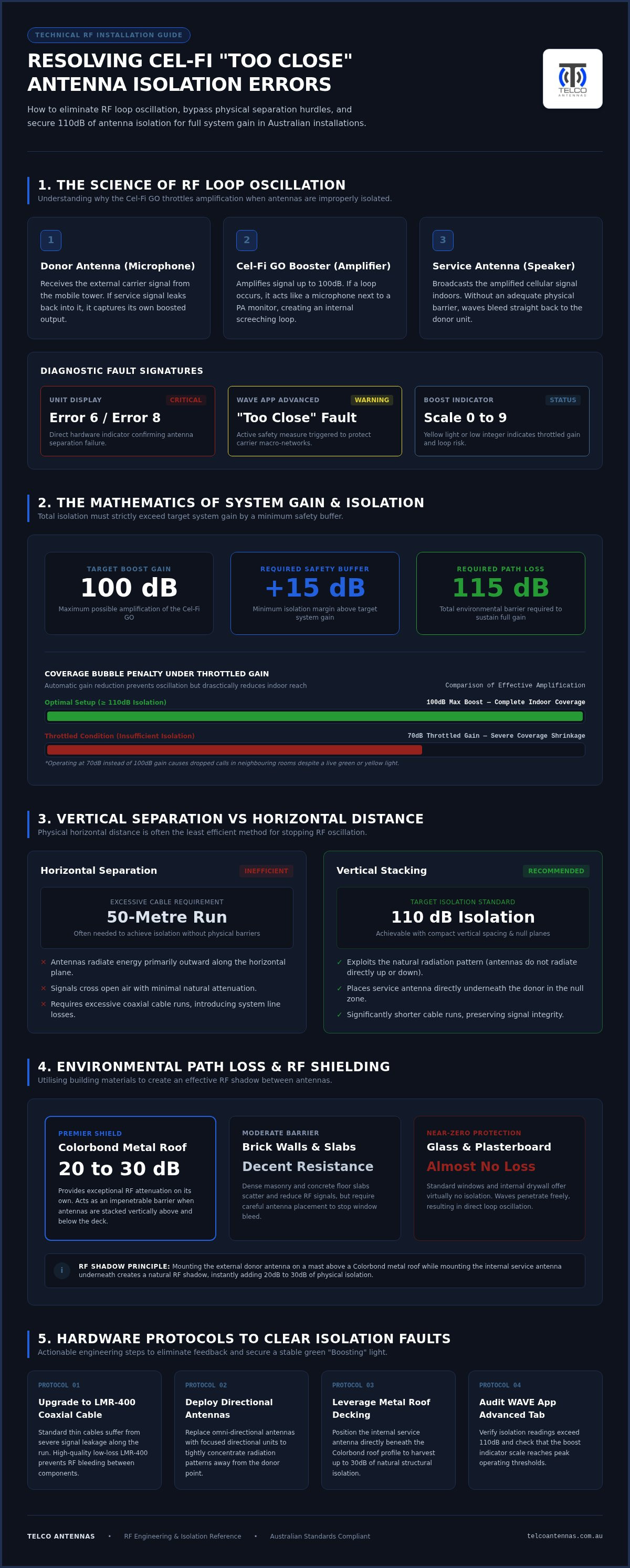
Hardware Solutions to Resolve Persistent Errors
When physical distance reaches its practical limit, the solution to a persistent cel-fi booster error code too close antenna separation fault often lies in the mechanical integrity of your hardware. Standard retail kits sometimes include entry-level components that are susceptible to signal leakage, effectively turning the entire installation into a massive feedback loop. Upgrading to professional-grade equipment can create the electromagnetic barriers that distance alone cannot provide, ensuring the system reaches its full 100dB gain potential.
The LMR-400 Advantage for Isolation
The most common point of failure in many DIY setups is the use of thin, poorly shielded RG-58 cabling. Because this cable has high attenuation and low shielding effectiveness, it can actually radiate signal along its entire length. This means the donor antenna can pick up signal leaking from the cable itself before it even reaches the service antenna. Upgrading to LMR-400 coaxial cables provides a double-shielded barrier that keeps the RF energy contained. Proper connector termination is equally vital; a poorly crimped N-type connector can create an RF "hot spot" that trips isolation sensors even if your antennas are 20 metres apart.
Directional Antennas and Beamforming
Switching from an omni-directional donor antenna to a directional Yagi or LPDA is another high-impact mechanical fix. While an omni-directional antenna listens in a 360-degree radius, a directional antenna focuses its sensitivity toward the cell tower and away from your building. For data-intensive applications in remote areas, a MIMO antenna configuration can improve both throughput and isolation by managing multiple signal paths. If you are mounting a donor antenna on a non-metal surface, such as a fibreglass caravan roof or a timber beam, you must install a metal ground plane or shielding plate underneath it. This plate acts as a physical barrier, reflecting the internal signal away from the donor's receiver.
You can also manipulate signal polarisation to squeeze out the last few decibels of isolation. Rotating your service antenna 90 degrees relative to the donor antenna can sometimes drop the feedback level enough to clear a "Too Close" error. Use the real-time signal meter in the WAVE app to monitor the impact of these hardware changes as you adjust the aim. If you are struggling to find the right combination of components for your specific environment, you can source professional-grade RF hardware to find the exact shielding solutions required for your site.
When to Seek Professional RF Engineering Support
If you have implemented significant vertical separation and upgraded to high-shielding cables but still encounter the cel-fi booster error code too close antenna separation fault, your environment likely suffers from complex multipath interference. This phenomenon occurs when the boosted signal reflects off highly conductive surfaces, such as large metal sheds, solar arrays, or adjacent commercial structures, and enters the donor antenna from an unexpected angle. In these specific scenarios, physical distance is a blunt tool that cannot resolve the feedback loop because the signal is not travelling in a straight line. Persistent oscillation is more than a nuisance; running a unit in a state of constant gain-throttling can lead to excessive heat buildup that may eventually degrade the internal processor.
Custom RF Design for Industrial and Remote Sites
For large-scale operations or complex multi-storey buildings, we move beyond the trial-and-error phase of DIY installation. Our engineering team utilises advanced software modelling to perform a predictive RF site survey before any hardware is permanently fixed to a structure. This technical approach allows us to map the precise location of "null zones" where electromagnetic isolation is naturally highest. In expansive remote environments, such as mining camps or agricultural hubs, we often integrate Cel-Fi hardware with long-range wireless bridges to distribute connectivity across vast distances. This managed deployment strategy ensures that corporate and government clients maintain strict compliance with network safety standards while guaranteeing a full 100dB system gain.
Contacting Telco Antennas for a Solution
Our team of Australian-based technicians possesses the expertise to troubleshoot your system by reviewing your WAVE app diagnostic logs remotely. This data-driven analysis often reveals hidden environmental variables that are not obvious to the naked eye. We provide a range of specialised services to ensure your equipment functions as intended. We supply pre-terminated, low-loss cable kits and high-isolation antenna arrays that are specifically tailored to the unique challenges of the Australian landscape. Whether you are dealing with a difficult 4WD canopy setup or a shielded industrial warehouse, we can provide the engineering oversight necessary to eliminate feedback errors for good.
Contact Telco Antennas today for expert advice on your Cel-Fi deployment and ensure your mobile coverage is both reliable and high-performing.
Maximising Your System Gain for Reliable Coverage
Resolving a cel-fi booster error code too close antenna separation fault requires a move from basic distance adjustments to a technical understanding of RF isolation. By prioritising vertical separation and utilising the natural shielding of your building or vehicle's structure, you can force the system out of its protective throttled state. High-quality components like double-shielded LMR-400 cable and directional antennas are not just optional extras; they are the mechanical tools that stop signal leakage at the source.
If your unique environment continues to trigger oscillation warnings, it is a sign that multipath reflections require professional intervention. Telco Antennas has been an Australian technical authority since 2008, specialising in LMR-400 low-loss cabling and expert RF engineering support. We provide the diagnostic experience needed to guarantee your system reaches its full 100dB potential. Solve your signal issues with a professional Cel-Fi GO kit from Telco Antennas. With the right hardware and a methodical approach to antenna placement, you can finally eliminate black spots and enjoy stable, high-speed mobile connectivity across your entire site.
Frequently Asked Questions
What is the minimum distance required between Cel-Fi antennas?
For a stationary installation aiming for 100dB gain, you typically require at least 15 metres of horizontal separation or 6 metres of vertical separation. Vertical distance is significantly more effective because it places the antennas in each other's radiation null points. In vehicle setups, achieving this distance is physically impossible, so you must rely on the metal roof as an RF shield to create the necessary isolation barrier between the donor and service antennas.
Can I use a metal plate to improve antenna isolation?
Yes, installing a metal plate or ground plane under a donor antenna is a highly effective method for improving isolation on non-conductive surfaces like fibreglass or timber. This plate acts as an electromagnetic shield, reflecting the internal signal away from the donor's receiver. For the best results, the plate should be at least 30cm in diameter to create a sufficient "RF shadow" and prevent the signal from wrapping around the edges of the mounting surface.
Why does my Cel-Fi GO show a red light after I move the antennas?
A red light persisting after moving your antennas indicates that the system has not yet recalibrated or the isolation is still below the required threshold. You should power-cycle the unit to force a fresh isolation measurement and clear the cache. If the red light returns, consult the WAVE app to see if the cel-fi booster error code too close antenna separation is still active, as even a small amount of signal leakage can prevent the system from booting.
Will a longer cable fix the 'too close' error code?
A longer cable provides the physical distance needed for isolation, but the cable type is often more important than the total length. If you use low-quality RG-58 cable, the signal can leak through the shielding, causing a "Too Close" error regardless of antenna distance. We recommend using double-shielded LMR-400 coaxial cable. This prevents the cable run itself from acting as an antenna and ensures the signal only exits where it is intended at the connector.
Does the type of antenna (omni vs directional) affect isolation?
Antenna type has a massive impact on system stability and isolation levels. Directional antennas, such as Yagis, focus their energy in one direction and have a "null" behind them, which naturally reduces feedback. Omni-directional antennas broadcast in 360 degrees, making them much harder to isolate in confined spaces like caravans. Switching to a directional donor antenna is often the most direct way to resolve persistent separation errors without moving your entire mounting setup or mast.
How do I check my isolation score in the Cel-Fi WAVE app?
To check your isolation, connect to your unit via Bluetooth and open the Cel-Fi WAVE app on your mobile device. Navigate to the "Advanced" tab and look for the "Isolation" value, which is measured in decibels (dB). For a Cel-Fi GO to achieve its maximum 100dB gain, this figure should ideally be 110dB or higher. If the value is lower, the unit will automatically reduce its power to prevent network interference.
Is Error 6 the same as antenna separation issues?
Yes, Error 6 is the specific hardware diagnostic code for an antenna separation failure on legacy Cel-Fi units. On modern hardware like the Cel-Fi GO G41 or G51, this often appears as a "Too Close" notification in the app or a specific flashing red LED pattern. Regardless of the label, the underlying issue remains the same: the donor antenna is picking up too much amplified signal from the internal service antenna, creating a loop.
Can I install my donor antenna on a bullbar and still get full gain?
Achieving full 100dB gain with a bullbar-mounted antenna is difficult because of the lack of vertical separation from the cabin. While common in Australia, bullbar mounts often result in reduced system gain unless you use a high-quality external antenna and place the internal antenna as low as possible. If you encounter a cel-fi booster error code too close antenna separation on a ute, moving the donor antenna to the roof rack is usually the only way to reach full power.


