
The most sophisticated radio hardware in the world is effectively useless if it's tethered to the wrong piece of copper. You've likely invested significantly in high-gain antennas and boosters, only to face unexplained signal drops or underwhelming throughput. It's a common frustration in the Australian telecommunications sector, where environmental factors often punish subpar components. Selecting the right rf cable isn't merely an accessory choice; it's a critical engineering requirement that determines the ultimate integrity of your signal path.
We understand that the jargon surrounding naming conventions, such as the distinction between LMR and RG series, often creates more confusion than clarity. This guide provides the technical framework you need to eliminate attenuation bottlenecks and ensure the long-term durability of your RF links. We'll examine the mechanical trade-offs between cable flexibility and performance, while addressing how to protect your infrastructure against harsh Australian UV and moisture ingress. By the end of this analysis, you'll have the expertise to specify the exact coaxial profile required for your specific frequency and distance parameters.
Key Takeaways
- Understand how the physical layers of an rf cable, from the centre conductor to the UV-stabilised jacket, directly impact signal attenuation and longevity in harsh Australian environments.
- Compare performance benchmarks between LMR-400 and RG-series alternatives to minimise decibel loss across critical 700MHz to 2600MHz frequency bands.
- Learn the technical impact of Velocity of Propagation (VoP) on signal timing and why dielectric quality is non-negotiable for high-value installations.
- Master a systematic selection framework that balances cable flexibility against performance requirements for various run lengths and environmental conditions.
- Identify the critical role of connector selection and professional installation in maintaining the long-term integrity of your telecommunications infrastructure.
Understanding RF Cable: The Foundation of Signal Integrity
An rf cable is a specialised coaxial transmission line engineered to transport high-frequency electromagnetic waves while protecting the signal from external interference. Unlike standard electrical wiring, the specific coaxial cable construction dictates how effectively a signal reaches its destination without degrading into noise. In the Australian telecommunications landscape, where remote sites and high-value industrial installations are common, signal integrity is the primary metric of success. If the cable fails to preserve the signal's amplitude and phase, the entire hardware chain becomes redundant.
Selecting a "cheap" cable often results in a permanent reduction in system performance, creating signal black spots that no amount of antenna adjustment can fix. This is a common failure point in professional deployments; the initial savings on a lower-grade cable are quickly eclipsed by the cost of troubleshooting and hardware replacement. High-quality cabling ensures that the link remains stable even when environmental variables, such as extreme heat or moisture, challenge the physical integrity of the installation.
The Role of Impedance in RF Systems
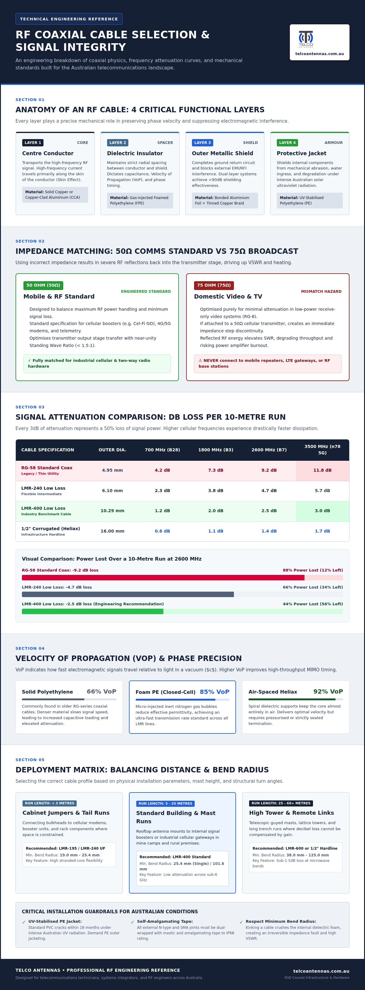
Impedance matching is a non-negotiable requirement for any efficient RF system. Most professional radio communications equipment, including mobile signal boosters like the Cel-Fi GO, operates on a 50-ohm standard. This is distinct from the 75-ohm standard used in domestic television and video applications. While the cables may look similar, using a 75-ohm cable in a 50-ohm system creates a significant impedance mismatch.
This mismatch leads to an increased Standing Wave Ratio (SWR), where a portion of the signal is reflected back toward the source rather than being transmitted through the antenna. High SWR doesn't just reduce signal strength; it generates heat and can cause permanent damage to the transmitter's output stage. For professional-grade comms, staying within the 50-ohm ecosystem is essential for both performance and hardware longevity.
Frequency Response and Bandwidth
The performance of an rf cable is not static; it changes significantly based on the frequency of the signal it carries. As you move from lower-frequency 4G bands up to higher-frequency 5G, Wi-Fi, or satellite bands, the rate of signal loss, known as attenuation, increases. This frequency-dependent loss is a physical reality of coaxial design. A cable that performs adequately at 700MHz might be entirely unsuitable for a 2600MHz or 3500MHz deployment because the dielectric and conductor materials absorb more energy at higher cycles. Understanding these attenuation curves is vital when specifying cable for modern, high-bandwidth applications.
Anatomy and Physics: Why Coaxial Cable Construction Matters
Every rf cable consists of four fundamental layers that work in concert to maintain signal integrity. At the core is the centre conductor, which is surrounded by the dielectric insulator, wrapped in a metallic shield, and protected by an outer jacket. The dielectric is a non-conductive insulating layer that maintains the precise physical spacing between the conductor and shield to ensure consistent impedance across the cable length. If this spacing varies even slightly, the resulting impedance mismatch causes signal reflections that degrade performance.
The physics of the dielectric also determines the Velocity of Propagation (VoP). This metric describes the speed at which a signal travels through the cable relative to the speed of light in a vacuum. High-quality dielectrics offer a higher VoP, which is essential for maintaining signal timing and phase alignment. In complex telecommunications systems, phase errors caused by poor VoP consistency can lead to data packet loss and reduced throughput, making the material science of the cable as important as its thickness.
Shielding effectiveness is another critical physical attribute. It prevents external electromagnetic interference from corrupting the data stream while simultaneously containing the RF energy within the cable. For professional Australian installations, especially those near high-interference industrial equipment, the quality of this shielding determines the baseline noise floor of the entire system. Understanding these mechanical variables is the first step in moving beyond commodity-grade components. If you require assistance specifying the correct physical build for your site, Telco Antennas provides the technical expertise to guide your selection.
Conductor Materials: Copper vs. Copper-Clad Aluminium
The choice of centre conductor material is a primary differentiator between consumer-grade and professional-grade cabling. High-frequency signals exhibit the "skin effect," where the current flows primarily on the outer surface of the conductor rather than through its core. While copper-clad aluminium (CCA) is lighter and less expensive, solid copper remains the standard for high-reliability Australian installations. Pure copper provides superior conductivity and better resistance to the mechanical stresses of installation, ensuring that the signal path remains stable over years of service in remote environments where maintenance is difficult.
Shielding and Interference Rejection
Effective shielding separates a functional rf cable from a source of system failure. In high-interference environments, dual-shielding, which combines a solid foil layer for high-frequency protection and a tinned copper braid for lower frequencies, is essential. This robust shielding preserves the Signal-to-Noise Ratio (SNR), which is particularly critical for MIMO antenna configurations where multiple data streams must remain distinct. You can find further technical details on shielding performance in the ARRL feed line guide, which highlights how different braid densities affect interference rejection.
Performance Benchmarks: Comparing LMR-400, LMR-240, and RG-Series
The LMR (Low Loss) series has redefined expectations for professional telecommunications by prioritising signal retention over manufacturing simplicity. While traditional coaxial cable construction focuses on basic connectivity, the LMR range is engineered to minimise attenuation across the wide bandwidths required by modern 4G and 5G networks. In any professional RF link, the cable is the primary source of signal loss, and choosing the correct grade is the only way to ensure your hardware performs to its theoretical specifications.
Attenuation rates vary significantly based on frequency. For a standard 10-metre run at 700MHz, an LMR-400 cable typically loses less than 1dB of signal. At the higher 2600MHz band used for high-speed data, that loss increases to approximately 2.2dB. In contrast, a standard RG-58 cable can lose over 10dB in the same 10-metre run at high frequencies. This difference isn't just a technical detail; it represents the difference between a high-speed data connection and a total link failure. If your installation involves long cable runs, relying on an inferior rf cable will inevitably create a bottleneck that compromises your entire network's throughput.
LMR-400: The Professional Choice for Fixed Wireless
LMR-400 is the industry standard for fixed site installations, particularly in communication tower design. Its 10.29mm diameter provides the physical volume necessary for a thick, high-performance dielectric and a solid copper centre conductor. We've observed cases where replacing a 10-metre RG-58 run with LMR-400 recovered up to 6dB of signal gain. That's equivalent to doubling the transmit power of the radio twice over. For Australian conditions, LMR-400 is typically manufactured with UV-stabilised jackets, ensuring the cable doesn't become brittle or crack under intense solar radiation.
LMR-240 and RG-58: When to Use Flexible Cables
There are specific scenarios where the rigidity of LMR-400 is a disadvantage. For short runs under 2 metres, such as internal equipment patches or vehicle-mounted antennas where routing is tight, LMR-240 offers a pragmatic middle ground. It's more flexible than LMR-400 but far superior to RG-series cables. While RG-58 is still widely available, it's increasingly obsolete for modern 5G deployments. Its high attenuation at frequencies above 2GHz makes it unsuitable for anything other than the shortest "pigtail" adapters. Selecting the right rf cable requires a balance of performance and practicality; you don't want to sacrifice 50% of your signal just for an easier installation path.
Selection and Installation: Optimising Your RF Infrastructure
Effective selection of an rf cable follows a methodical framework designed to prevent system underperformance. Every decibel lost within the cable run is a decibel that even the highest-gain antenna cannot recover, making the feed line the most critical link in your link budget. To ensure success, follow this five-step process:
- Identify Frequency: Determine the peak operational frequency of your hardware.
- Measure Length: Calculate the exact run length, accounting for vertical rises and routing detours.
- Assess Environment: Evaluate UV intensity, moisture levels, and coastal salt spray.
- Balance Flexibility: Determine if your routing requires the pliability of LMR-240 or the low loss of LMR-400.
- Specify Connectors: Match connectors (SMA, N-Type, TNC) to your hardware's impedance.
Installation quality is as important as the cable specification itself. The most frequent error in the field is exceeding the minimum bend radius. If an rf cable is forced into a tight corner, the internal dielectric is crushed, which permanently alters the concentric geometry between the conductor and the shield. This deformation creates an impedance mismatch that reflects signal back to the transmitter. Similarly, selecting the correct connector ensures that the physical transition between components doesn't introduce unnecessary loss. For those requiring pre-terminated, high-performance links, you can source professional LMR-400 cable assemblies designed for Australian industrial standards.
Calculating Your Link Budget
A link budget is a mathematical accounting of all gains and losses in your RF path. To calculate total cable loss, multiply the manufacturer's attenuation rating per metre by your total length, then add approximately 0.2dB for each connector pair. This calculation is vital when deploying a wireless bridge, where you must maintain a sufficient fade margin. A fade margin acts as a safety buffer against atmospheric changes; without it, even a minor increase in cable attenuation can drop the link entirely.
Ruggedising for the Australian Environment
Australian conditions demand specific ruggedisation techniques to ensure long-term durability. All outdoor connections should be wrapped in self-amalgamating tape followed by a UV-rated PVC overwrap to prevent moisture ingress. In mobile deployments or when using a mast trailer, cables must be secured with cushioned clamps to mitigate vibration-induced fatigue. Long vertical runs also require consideration for thermal expansion. As the jacket and core expand at different rates in the midday sun, cable hangers must allow for slight movement to prevent tension on the connectors.
Professional RF Solutions: Engineering the Perfect Link
Treating an rf cable as a simple commodity is a frequent error in telecommunications procurement. In a professional deployment, every component must be viewed through the lens of engineering precision. A generic cable might connect two points, but only a correctly specified, high-performance link ensures that the system operates at its maximum theoretical capacity. This is particularly relevant for those integrating high-gain antennas into Starlink accessories for remote Australian sites, where signal margin is often slim and environmental conditions are unforgiving.
Custom-terminated cable assemblies offer a distinct advantage over generic, off-the-shelf kits. By specifying the exact length required for an installation, you eliminate the need for excess cable coils, which act as unnecessary inductors and sources of signal loss. Furthermore, custom assemblies allow for the selection of specific connector combinations that match your hardware without the use of lossy adapters. This level of customisation ensures that the transition from the antenna to the radio equipment remains as efficient as possible, preserving the signal-to-noise ratio that modern high-speed data links require.
Consultative Engineering Services
Telco Antennas utilises comprehensive RF site surveys to determine the precise cabling requirements for complex infrastructure projects. These surveys allow our technical team to identify the optimal cable path and grade based on real-world situational variables rather than theoretical models. By assessing local interference profiles and physical obstructions before deployment, we reduce the risk of post-installation signal drops. This consultative approach transforms the selection of an rf cable from a guessing game into a calculated engineering decision, providing a reliable foundation for critical communication links.
Why Quality Infrastructure Matters
The long-term return on investment for LMR-series cabling is found in its reliability and performance stability. In remote industrial environments, the cost of a single site visit to troubleshoot a degraded connection can far exceed the initial investment in professional-grade hardware. High-quality cabling, characterised by solid copper conductors and UV-stabilised jackets, maintains its electrical properties for years, even under the intense Australian sun. Choosing the correct infrastructure today prevents the costly bottlenecks and black spots of tomorrow. If you are planning a new deployment or upgrading existing hardware, contact the Telco Antennas engineering team to discuss your RF cable requirements.
Securing Your Signal Path with Precision Engineering
Selecting the right rf cable is the difference between a system that merely exists and one that truly performs. It determines your reach. We've examined how physical construction, from the dielectric properties to the shielding density, dictates the ultimate success of your telecommunications link. By prioritising low-loss standards like LMR-400 over generic alternatives, you eliminate the attenuation bottlenecks that often plague high-frequency installations in the Australian climate.
Telco Antennas has been a specialist in high-frequency RF infrastructure since 2008, providing the technical authority required for complex deployments. Our team offers technical engineering support for every purchase to ensure your hardware is correctly matched to its environment. We also provide custom cable termination services to meet your exact site specifications, which reduces unnecessary signal loss from excess length or lossy adapters. Investing in quality infrastructure today ensures your network, whether it's a Cel-Fi booster or a Starlink deployment, remains resilient against environmental degradation and evolving bandwidth demands. Browse our range of professional LMR-400 coaxial cables and custom assemblies to secure your connectivity.
Frequently Asked Questions
What is the difference between RG-58 and LMR-400 cable?
RG-58 is a thin, high-loss cable primarily suited for short internal pigtails or low-frequency applications. In contrast, LMR-400 is a thick, low-loss rf cable designed for fixed infrastructure and high-frequency 4G or 5G signals. While RG-58 might lose half your signal strength over just five metres at high frequencies, LMR-400 maintains signal integrity over much longer distances. Choosing LMR-400 ensures your hardware performs to its full engineering potential.
How much signal loss does 10 metres of coaxial cable cause?
Signal loss over 10 metres is entirely dependent on the cable grade and the frequency being transmitted. For example, LMR-400 typically loses less than 1dB at 700MHz, but this increases to roughly 2.2dB at 2600MHz. Lower-quality cables like RG-58 can lose upwards of 10dB over the same distance at high frequencies. Always consult an attenuation chart for your specific frequency to ensure your link budget remains within operational parameters.
Can I use 75-ohm TV cable for my mobile signal booster?
You should not use 75-ohm cable for a mobile signal booster. Professional telecommunications equipment, including the Cel-Fi GO, is engineered for a 50-ohm impedance standard. Using 75-ohm TV cable—the standard for professional audio-visual setups found at hdtvsupply.com—creates a significant impedance mismatch, leading to a high Standing Wave Ratio (SWR). This mismatch causes signal reflections that reduce system efficiency and can potentially damage the transmitter's internal components over time. Always match your cable's impedance to your hardware.
There isn't a hard universal limit, but we generally recommend keeping LMR-400 runs under 30 metres for most mobile signal applications. Beyond this length, the cumulative decibel loss often negates the gain provided by your antenna. If your site requires a longer run, you may need to specify an even higher grade of low-loss rf cable or consider an active solution. A professional site survey can help determine the exact limits for your specific location.
Why are connectors just as important as the cable itself?
Connectors are the critical transition points where signal reflections and moisture ingress most commonly occur. A poorly installed or low-quality connector introduces impedance bumps that increase SWR and degrade throughput. Even the best cable cannot compensate for a loose crimp or a corroded interface. Selecting high-quality N-Type or SMA connectors, and ensuring they are correctly torqued, is essential for maintaining the long-term electrical integrity of your entire telecommunications system.
How do I protect my RF cable connections from the Australian weather?
Protecting connections from the Australian climate requires a dual-layer approach. First, wrap the connection in self-amalgamating tape, which fuses into a waterproof mass to prevent moisture ingress. Follow this with a layer of UV-stabilised PVC electrical tape to protect the amalgamating layer from solar degradation. This method is particularly vital in coastal areas where salt spray can rapidly corrode exposed metallic threads, leading to permanent signal failure and hardware damage.
Does a thicker RF cable always mean better performance?
Generally, a thicker cable provides better performance because it accommodates a larger centre conductor and a more substantial dielectric layer. These physical attributes reduce attenuation and improve power handling. However, thickness alone isn't the only factor; the quality of the materials and the shielding effectiveness also play vital roles. The primary trade-off is flexibility. Thicker cables like LMR-400 have a much larger minimum bend radius, making them harder to route through tight internal spaces.
Can I join two RF cables together without losing signal?
You can join two cables using a high-quality barrel connector, but it isn't recommended for high-performance links. Every physical join introduces a small amount of signal loss, typically between 0.2dB and 0.5dB, and creates a potential point of failure for moisture ingress. For critical infrastructure, a single continuous cable run is always the superior engineering choice. If you must use a join, ensure it is properly weatherproofed and tightened to maintain consistent impedance.


